Non-uniform curved surface fly-eye lens and preparation method thereof

A technology of curved compound eyes and lenses, applied in lenses, optics, instruments, etc., can solve problems such as defocusing

Active Publication Date: 2021-03-30
CHANGCHUN INST OF OPTICS FINE MECHANICS & PHYSICS CHINESE ACAD OF SCI
View PDF5 Cites 1 Cited by
  • Summary
  • Abstract
  • Description
  • Claims
  • Application Information

AI Technical Summary

Problems solved by technology

At the same time, it solves the defocus problem caused by the mismatch between the focal plane of the curved surface and the

Method used


Image

  • Non-uniform curved surface fly-eye lens and preparation method thereof
  • Non-uniform curved surface fly-eye lens and preparation method thereof
  • Non-uniform curved surface fly-eye lens and preparation method thereof

Examples


Embodiment

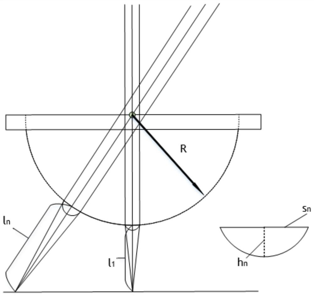
[0050] figure 1 A schematic diagram of the design method of a non-uniform curved surface compound eye lens of the present invention is shown.

[0051] Such as figure 1 As shown, it is an innovative design scheme of a double pumping curved surface fly eye lens. The core idea of ​​the design of the non-uniform sub-eye is to make the focal length of each sub-eye different. non-uniform arrangement to achieve. Light rays of different angles enter from the plane end of the curved surface fly-eye lens and exit from the curved surface end, which coincides with the optical axis of each sub-eye. Assuming that the central sub-eye is a first-level sub-eye, the distance from it to CMOS is l 1 , it can be defaulted that its object-space focal length f′ is equal to l 1 , extending from the first-level sub-eye to the periphery, respectively l 2 , l 3 ...l m , l m As the number of sub-eyes increases, the larger the value, the defocus problem of the curved surface fly-eye lens is solved...


PUM


Abstract

The invention provides design of a non-uniform curved surface fly-eye lens and a preparation method of the same. The method comprises the steps of: setting sub-eyes, with different calibers and vectorheights, of all levels on the curved surface fly-eye lens, and acquiring different sub-eye focal lengths of all levels; enabling light to enter from the plane end of the curved surface fly-eye lens and exit from the curved surface end, wherein light at different angles passes through the optical center of the sub-eye, so that all light refraction focuses fall on the same plane; and taking the central sub-eye through which light enters in a manner of being perpendicular to the plane end of the curved surface fly-eye lens as a primary sub-eye. The non-uniform curved surface fly-eye lens is prepared by utilizing twice air pressure assistance and an ultraviolet curing process, the time is short, the efficiency is high, the repeatability is good, and the surface appearance is uniform.

Description

technical field [0001] The invention is designed in the field of micro-nano processing, mainly a new design scheme and preparation method of compound eyes with non-uniform curved surfaces. Background technique [0002] In contemporary times, microlenses are currently widely used in detection and imaging systems in the fields of national defense, medicine and civilian use. With an optical imaging system composed of a single lens, it is difficult to obtain a wide field of view. Only a fisheye lens can be larger than 90°. At the same time, this traditional optical imaging system usually uses a lens group for imaging, which has a large number of lenses, a large volume, and a complex structure, making it difficult to integrate and integrate with various miniaturized systems. [0003] On the basis of the microlens array research, the researchers were inspired by the compound eyes of insects and hoped to integrate an artificial compound eye imaging system. The curved surface comp...

Claims


Application Information

Patent Timeline
IPC IPC(8): G02B3/00G02B27/00
CPCG02B3/0031G02B27/0012
Inventor 刘永顺陶可楷连高歌吴一辉
Owner CHANGCHUN INST OF OPTICS FINE MECHANICS & PHYSICS CHINESE ACAD OF SCI
Why Eureka
Try Eureka