
A Liquid Bridge Generator

A generator and liquid bridge technology, applied in the field of fluid physics, can solve the problems of complex structure and single function of liquid bridge generation equipment

Active Publication Date: 2022-02-22
NORTHEASTERN UNIV LIAONING
View PDF0 Cites 0 Cited by
  • Summary
  • Abstract
  • Description
  • Claims
  • Application Information

AI Technical Summary

Problems solved by technology

[0003] However, the experimental research on the influence of different airflow conditions, temperature conditions and magnetic field conditions on the liquid bridge interface is still in its infancy, and the few experimental researches cannot be widely promoted because of the complex structure and single function of the liquid bridge generation equipment.

Method used


Image

  • A Liquid Bridge Generator
  • A Liquid Bridge Generator
  • A Liquid Bridge Generator

Examples


Embodiment Construction

[0032] The following will clearly and completely describe the technical solutions in the embodiments of the present invention with reference to the drawings in the embodiments of the present invention. Apparently, the described embodiments are only some of the embodiments of the present invention, not all of them.

[0033] In describing the present invention, it should be understood that the terms "longitudinal", "transverse", "vertical", "upper", "lower", "front", "rear", "left", "right", The orientation or positional relationship indicated by "vertical", "horizontal", "top", "bottom", "inner", "outer", etc. is based on the orientation or positional relationship shown in the drawings, and is only for the convenience of describing the present invention and The description is simplified rather than indicating or implying that the device or element referred to must have a particular orientation, be constructed and operate in a particular orientation. Therefore, it should not be...


PUM


Abstract

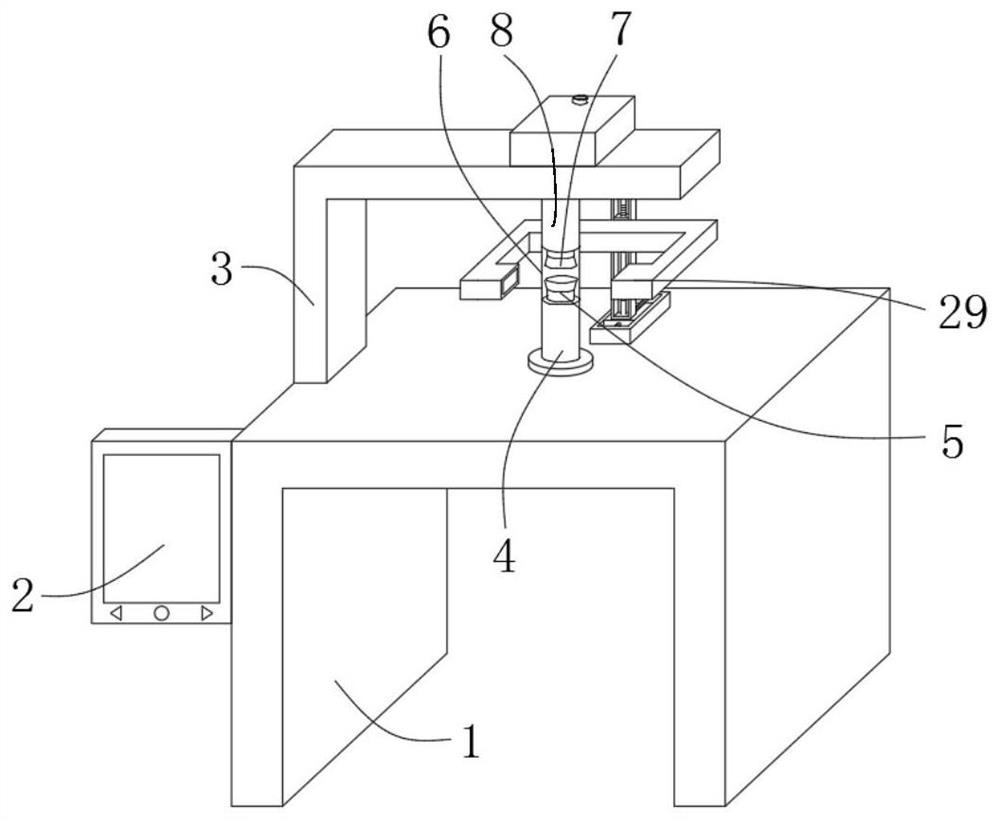
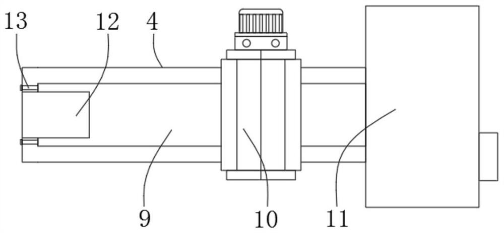
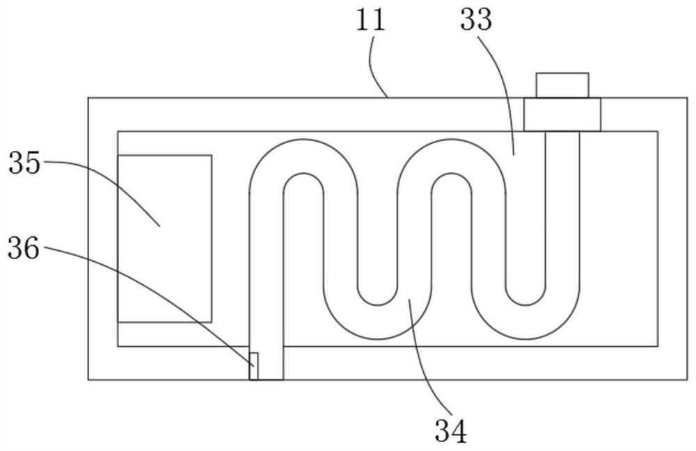
A liquid bridge generator belongs to the technical field of fluid physics. The liquid bridge generator includes a frame, a lower air intake assembly is installed at the top center of the frame, and a lower plate is installed at the top center of the lower air intake assembly; a bracket is installed at the top of the frame , the upper air intake assembly corresponding to the lower air intake assembly is installed on the support, the upper plate is installed at the bottom center of the upper air intake assembly, and the experimental liquid is injected between the lower plate and the upper plate to form a liquid bridge; The lower air intake assembly and the upper air intake assembly are respectively connected to the fan, and the lower air intake assembly and the upper air intake assembly are connected through an observation sleeve; the top of the frame is installed outside the observation sleeve. A magnetic field component; a control terminal is installed on one side of the frame, and a PLC controller is installed inside the control terminal. The liquid bridge generator can realize the influence of different air flow, temperature and magnetic field on the liquid bridge interface.

Description

technical field [0001] The invention relates to the technical field of fluid physics, in particular to a liquid bridge generator. Background technique [0002] The floating zone method is a method of growing semiconductor crystal materials. The main principle of the floating zone method is that the material rod is heated by the outside, and the melting zone is supported between two solid material ends, and the heated melting zone is gradually pulled to grow the crystal. The quality is affected by the periodic oscillating capillary convection in the melting zone, which in turn produces micron-scale impurity streaks. The liquid bridge is based on the preparation of single crystals by the floating zone method, and is an ideal physical experimental model established to study the suppression of periodic oscillatory capillary convection during the crystal growth process. [0003] However, the experimental research on the influence of different airflow conditions, temperature cond...

Claims


Application Information

Patent Timeline
Patent Type & Authority Patents(China)
IPC IPC(8): G09B23/12C30B13/00C30B13/28C30B30/04
CPCG09B23/12C30B13/00C30B13/28C30B30/04
Inventor 梁儒全梁阳
Owner NORTHEASTERN UNIV LIAONING
Learn More