A Self-excited Oscillating Pulse Swirl Supercharger

A technology of self-excited oscillation and supercharger, which is applied in the direction of conveying bulk materials, transportation and packaging, conveyors, etc., to reduce processing difficulty and cost, and achieve good pulse effects

Inactive Publication Date: 2019-10-11
CHINA UNIV OF MINING & TECH
View PDF6 Cites 0 Cited by
  • Summary
  • Abstract
  • Description
  • Claims
  • Application Information

AI Technical Summary

Problems solved by technology

[0005] The self-excited oscillation pulse jet technology has been developed for nearly thirty years, and the theory is relatively mature. The theory of self-excited oscillation pulse jet has a huge application range in the field of hydraulic jet, but there are few applications of pulse jet theory applied to the field of pneumatic conveying. And there is no self-excited oscillation pulse swirl supercharger with simple structure, easy processing, good effect and low cost.

Method used


Image

  • A Self-excited Oscillating Pulse Swirl Supercharger
  • A Self-excited Oscillating Pulse Swirl Supercharger
  • A Self-excited Oscillating Pulse Swirl Supercharger

Examples


Embodiment 1

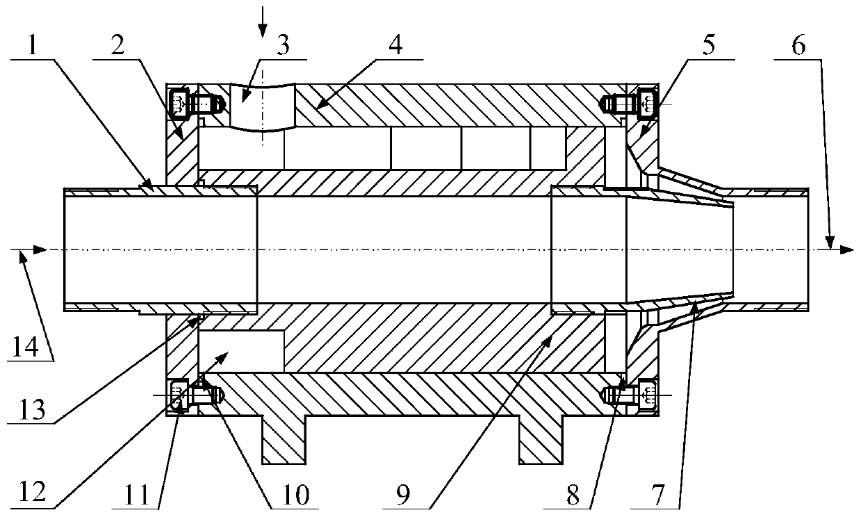
[0041] During the operation of the equipment, the air inlet 14 and the air supply port 3 use different positive pressure air sources, the powder will settle due to its own weight, accumulate in the lower part of the pipeline to form a powder mound, and continue to increase, resulting in a smaller cross-sectional area of ​​the main air duct and an increase in wind pressure. In order to reduce energy consumption and reduce pipeline wear, long-distance pneumatic transportation of materials often uses low-pressure air volume. When the wind pressure is not enough to blow through the piles of materials accumulated in the pipeline, pipeline blockage will occur.

[0042] When the air is replenished from the air supply port 3, the strong air flow enters the main pipeline through the central axis 9 of the pulse swirl, and flows out from the blocked rear end of the pipeline, forming a turbulent flow, disturbing and dividing the material pile and moving forward until the clogged material ma...

Embodiment 2

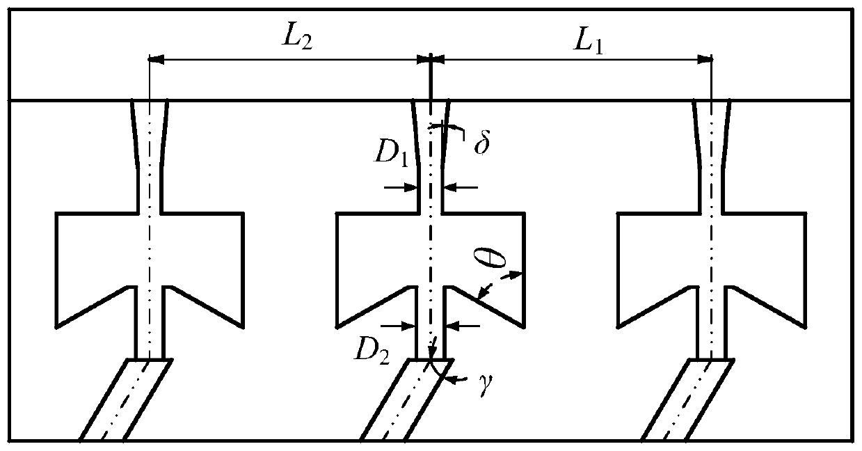
[0044] The outlet gas regulating pipe 7 of the pulse swirl supercharger adopts the end reducer structure. When the gas velocity is low, the material will be accumulated inside the supercharger. At this time, the pulse swirl supercharger acts as the first embodiment; when the gas velocity When the speed is sufficient to prevent the particles from clogging in the supercharger, that is, when the particles can pass through the cyclone supercharger smoothly, the tapered inclination angle design of the outlet regulating pipe 7 can make the particles be disturbed when passing through the outlet regulating pipe, so that The particles move along the entire pipeline to the outlet instead of sliding or rolling with the bottom of the pipeline, and when the diameter of the pipeline decreases, the velocity of the flow field will increase, and the material can be accelerated within a certain distance. The full pipe transportation of materials can not only prevent pipeline blockage, but also r...


PUM


Abstract

The invention provides a self-oscillation type pulse cyclone supercharger. The self-oscillation type pulse cyclone supercharger comprises a shell, an air inlet adjusting pipe, a left end cover, a pulse cyclone blade, an air outlet adjusting pipe and a right end cover; a main air inlet and a main air outlet are formed in the left end and the right end of the shell correspondingly; the left end cover and the right end cover of the shell are fixed through an M8 screw; the pulse cyclone blade is arranged inside the shell; the air inlet adjusting pipe is installed at the left end of the pulse cyclone blade; the air outlet adjusting pipe is installed at the right end of the pulse cyclone blade; two supporting leg bases are welded to the shell; the pulse cyclone blade comprises a center sleeve pipe and a cyclone blade arranged at the concave portion of the center sleeve pipe; particles and gas in the center sleeve pipe flow in the axial direction; a pulse cyclone air flow is formed between the shell and the pulse cyclone blade; and an auxiliary supplementing air inlet is formed in the shell and is in G1 pipe threaded connection. The self-oscillation type pulse cyclone supercharger is wide in application range, can reduce the minimum conveying speed of the particles, relieve the pipe abrasion, reduce particle crushing and avoid pipe blockage, and is suitable for pneumatic long-distance conveying of material particles.

Description

technical field [0001] The invention belongs to the technical field of pneumatic conveying, and in particular relates to a self-excited oscillation pulse swirl supercharger capable of converting continuous airflow into pulsed airflow. Background technique [0002] Pneumatic conveying technology is to use high-speed airflow to realize pneumatic conveying of bulk materials (such as flour, wheat, concrete materials, etc.) in the pipeline. At present, the use of pneumatic conveying generally adopts axial airflow pneumatic conveying. Pneumatic conveying has the advantages of cleanliness, environmental protection, and safety, but it also has disadvantages such as large power consumption, easy material breakage, and pipeline blockage. In order to improve the above problems, methods such as reducing the conveying speed and staged air supply and boosting can be adopted. Among them, the pneumatic conveying of the vortex airflow changes the form of the conveying airflow, changing from ...

Claims


Application Information

Patent Timeline
Patent Type & Authority Patents(China)
IPC IPC(8): B65G53/66
Inventor 刘送永纪云周甲伟江红祥吴洪状程诚李伟沈刚唐玮李洪盛周方跃
Owner CHINA UNIV OF MINING & TECH
Why Eureka
Try Eureka