Control rod driving mechanism with safety protection function

A technology of safety protection and driving mechanism, which is applied in the field of nuclear reactors, can solve problems such as failure to ensure safe shutdown of the reactor, reactor swing, and escape, and achieve reliable safety protection functions, safe shutdown, and compact structure.

Pending Publication Date: 2021-03-30
CHINA NUCLEAR POWER TECH RES INST CO LTD +2
View PDF0 Cites 1 Cited by
  • Summary
  • Abstract
  • Description
  • Claims
  • Application Information

AI Technical Summary

Problems solved by technology

[0002] As we all know, some reactors are in a periodical swing state, especially under extreme environmental conditions, the reactor will swing at a large inclination angle, or even tip over
[0003] At present, the reactor control rod drive mechanism used at home and abroad is not equipped with a safety protection mechanism with a tipping and locking function. Although the reactor control rod drive mechanism can also realize the function of dropping the control rod when the reactor is swaying at a small angle, it ensures the safety of the reactor. safe shutdown of the reactor; and when a large inclination angle swings or even overturns, the control rod assembly inserted into the bottom of the core may come out of the core, so that the safe shutdown of the reactor cannot be guaranteed

Method used


Image

  • Control rod driving mechanism with safety protection function
  • Control rod driving mechanism with safety protection function
  • Control rod driving mechanism with safety protection function

Examples


Embodiment Construction

[0022] Embodiments of the present invention will now be described with reference to the drawings, in which like reference numerals represent like elements.

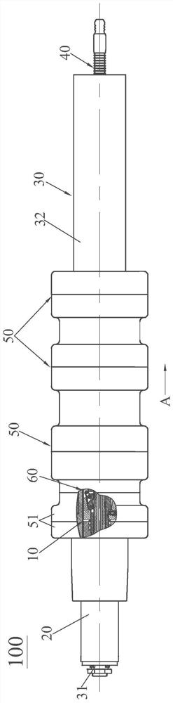
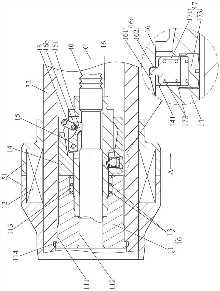
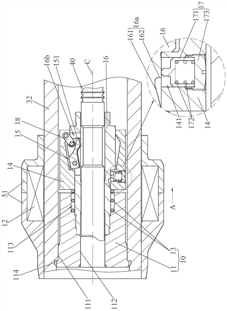
[0023] see figure 1 and figure 2 , The control rod driving mechanism 100 with safety protection function of the present invention includes a safety protection device 10 , a rod position detector assembly 20 , a pressure casing assembly 30 , a driving rod assembly 40 , a coil assembly 50 and a claw assembly 60 . The rod position detector assembly 20 is set on the stroke sleeve 31 in the pressure-resistant shell assembly 30, so as to give the actual position signal of the drive rod assembly 40 when the control rod drive mechanism 100 of the present invention is in operation; the hook assembly 60 is set in the sealing shell 32 of the pressure-resistant shell assembly 30, preferably suspended in the sealing shell 32, for realizing the functions of grasping, lifting, and inserting the driving rod assembly 40; the driving rod...


PUM


Abstract

The invention discloses a control rod driving mechanism with a safety protection function. The control rod driving mechanism comprises a rod position detector assembly, a pressure-resistant shell assembly, a claw assembly, a driving rod assembly, a coil assembly and a safety anti-expansion device. A safety protection device comprises a tipping magnetic pole, a tipping locking coil, a tipping spring, a tipping armature, a tipping claw and a transition supporting sleeve. A sealing shell is fixed to the transition supporting sleeve through the tipping magnetic pole, and the transition supportingsleeve is connected with the claw assembly in an assembled mode. The tipping armature is arranged on the transition support sleeve in a sliding manner; one end of the tipping spring elastically abutsagainst the tipping armature, and the other end of the tipping spring elastically abuts against the tipping magnetic pole or the transition supporting sleeve. The tipping claw is arranged on the transition supporting sleeve and is linked with the tipping armature; the driving rod assembly is arranged on the transition supporting sleeve and the tipping magnetic pole in a penetrating manner; the tipping locking coil is installed on the coil assembly, and the tipping armature is in linkage with the tipping claw in the axial sliding process to do pivot swing motion of being engaged with or disengaged from the driving rod assembly. Therefore, the safety function of tipping and locking is achieved, and safe shutdown of the reactor is achieved.

Description

technical field [0001] The invention relates to the field of nuclear reactors, in particular to a control rod driving mechanism with a safety protection function. Background technique [0002] As we all know, when some reactors are in a periodical swing state, especially under extreme environmental conditions, the reactor will swing at a large inclination angle, or even overturn. [0003] At present, the reactor control rod drive mechanism used at home and abroad is not equipped with a safety protection mechanism with a tipping and locking function. Although the reactor control rod drive mechanism can also realize the function of dropping the control rod when the reactor is swaying at a small angle, it ensures the safety of the reactor. When a large tilt angle swings or even overturns, the control rod assembly inserted into the bottom of the core may come out of the core, so that the safe shutdown of the reactor cannot be guaranteed. [0004] Therefore, there is an urgent n...

Claims


Application Information

Patent Timeline
Patent Type & Authority Applications(China)
IPC IPC(8): G21C19/105G21C19/02G21C7/14
CPCG21C7/14G21C19/105G21C19/02Y02E30/30G21C9/00
Inventor 卢朝晖陈叶青靳书武李泽文刘亚男刘青松周国丰芮旻唐叔建路广遥胡伦宝张超乔建毅苏晓炜
Owner CHINA NUCLEAR POWER TECH RES INST CO LTD
Why Eureka
Try Eureka