Control rod driving mechanism and anti-deflection claw assembly thereof

An anti-deflection and hooking claw technology, which is applied in the field of nuclear reactors, can solve the problems of reducing the reliability and service life of the control rod driving mechanism, the control rod driving mechanism cannot keep a fixed vertical state, and the moving armature of the hooking claw assembly is deflected. Reliability and service life, simple and compact construction, wear-reducing effect

Pending Publication Date: 2021-03-30
CHINA NUCLEAR POWER TECH RES INST CO LTD +2
View PDF1 Cites 0 Cited by
  • Summary
  • Abstract
  • Description
  • Claims
  • Application Information

AI Technical Summary

Problems solved by technology

[0002] As we all know, in the occasions where the reactor will be in complex working conditions such as periodic swinging and tilting, the control rod drive mechanism operating in this occasion will not be able to maintain a fixed vertical state, and changes in the operating environment will affect the action of the claw assembly
[0003] At present, for example, in the step-by-step magnetic lifting reactor control rod drive mechanism disclosed in Chinese Patent Application No. 200710050738.9, it can operate normally in the vertical working state, but in complex working conditions such as tilting and swinging, the control rod The driving mechanism will always be in a swinging or tilting state, which will cause a relative deflection tendency for the moving armature of the hook assembly. At this time, a harmful additional force will be exerted on the moving parts of the moving hook, which will aggravate the wear of the contact surface , reducing the reliability and service life of the control rod drive mechanism

Method used


Image

  • Control rod driving mechanism and anti-deflection claw assembly thereof
  • Control rod driving mechanism and anti-deflection claw assembly thereof
  • Control rod driving mechanism and anti-deflection claw assembly thereof

Examples


Embodiment Construction

[0039] Embodiments of the present invention will now be described with reference to the drawings, in which like reference numerals represent like elements.

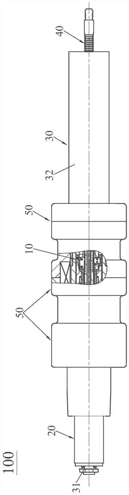
[0040] see figure 1 , The control rod driving mechanism 100 of the present invention includes an anti-deflection hook assembly 10 , a rod position detector assembly 20 , a pressure casing assembly 30 , a driving rod assembly 40 and a coil assembly 50 . The rod position detector assembly 20 is set on the stroke sleeve 31 in the pressure-resistant shell assembly 30, so as to give the actual position signal of the drive rod assembly 40 when the control rod drive mechanism 100 of the present invention is in operation; the drive rod assembly 40 is installed in the sealing shell 32; the coil assembly 50 is set outside the sealing shell 32, and is used to provide power for the action of the anti-deflection hook assembly 10; The gripping, lifting, and inserting functions of the rod assembly 40, while the driving rod assembly 40 ...


PUM


Abstract

The invention discloses a control rod driving mechanism and an anti-deflection claw assembly. The anti-deflection claw assembly comprises an upper end component, a lifting armature, a moving armature,a claw, a retaining magnetic pole, a retaining armature, a claw supporting sleeve, a lower end component, a buffer pipe shaft, a guide key and a sleeve shaft. The buffer pipe shaft is sleeved with the sleeve shaft, the guide key is embedded in the buffer pipe shaft, and the upper end component, the lifting armature, the movable armature, the maintaining magnetic pole, the maintaining armature, the claw supporting sleeve and the lower end component are sequentially distributed. The claw is arranged on the buffer pipe shaft and is linked with the moving armature; one of the moving armature andthe guide key is provided with an axial guide recess, and the other one of the moving armature and the guide key is provided with an axial guide bulge; the axial guide bulge is embedded in the axial guide recess and axially slides in the axial guide recess; abrasion of the anti-deflection claw assembly under complex working conditions such as swing and inclination is reduced, and reliable operation of the control rod driving mechanism is ensured.

Description

technical field [0001] The invention relates to the field of nuclear reactors, in particular to a control rod driving mechanism and an anti-deflection claw assembly thereof. Background technique [0002] As we all know, in the occasions where the reactor will be in complex working conditions such as periodic swinging and tilting, the control rod drive mechanism operating in this occasion will not be able to maintain a fixed vertical state, and changes in the operating environment will affect the action of the claw assembly . [0003] At present, for example, in the step-by-step magnetic lifting reactor control rod drive mechanism disclosed in Chinese Patent Application No. 200710050738.9, it can operate normally in the vertical working state, but in complex working conditions such as tilting and swinging, the control rod The driving mechanism will always be in a swinging or tilting state, which will cause a relative deflection tendency for the moving armature of the hook as...

Claims


Application Information

Patent Timeline
Patent Type & Authority Applications(China)
IPC IPC(8): G21C19/105G21C7/14
CPCG21C7/14G21C19/105Y02E30/30
Inventor 卢朝晖陈叶青李泽文刘亚男胡伦宝靳书武刘青松周国丰芮旻唐叔建路广遥张超乔建毅苏晓炜
Owner CHINA NUCLEAR POWER TECH RES INST CO LTD
Why Eureka
Try Eureka