Motor and motor manufacturing method
A technology made of motors and resins, applied to the manufacture of motor generators, casings/covers/supports, electrical components, etc., to achieve the effect of ensuring water resistance
- Summary
- Abstract
- Description
- Claims
- Application Information
AI Technical Summary
Problems solved by technology
Method used
Image
Examples
no. 1 Embodiment approach >
[0024]
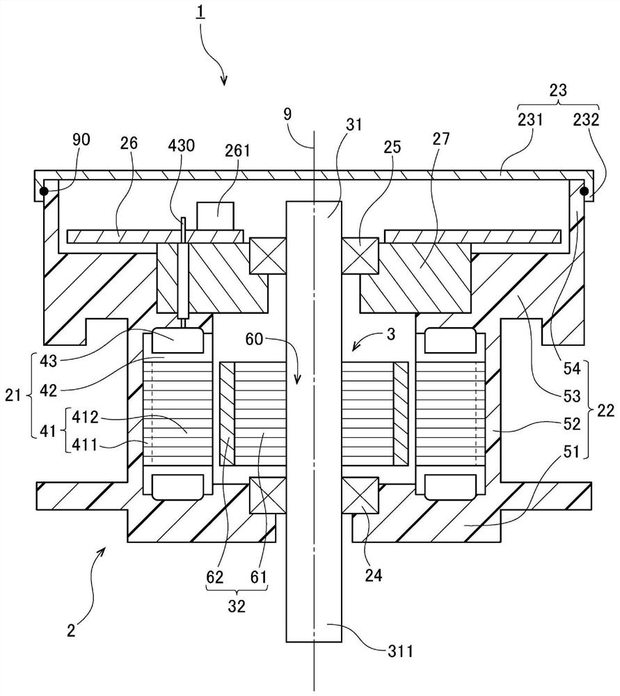
[0025] figure 1 It is a vertical cross-sectional view of the motor 1 according to the first embodiment of the present invention.
[0026] The motor 1 is mounted, for example, in an automobile, and is used as a driving source for generating a driving force of an electric power steering device. However, the motor of the present invention can also be used for purposes other than power steering. For example, the motor of the present invention can also be used as a driving source for other parts of an automobile such as a transmission device, a brake device, an engine cooling fan, or an oil pump. In addition, the motor of the present invention may be mounted on home appliances, OA equipment, medical equipment, etc., and generate various driving forces.
[0027] like figure 1 As shown, the motor 1 has a stationary part 2 and a rotating part 3 . The stationary unit 2 is fixed to a housing of a device to be driven. The rotating part 3 is supported so as to be rotatable...
no. 2 Embodiment approach >
[0054]
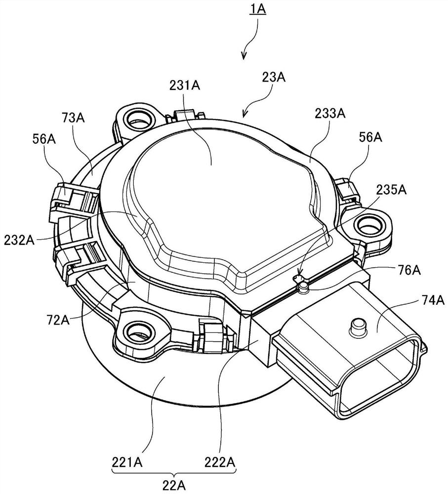
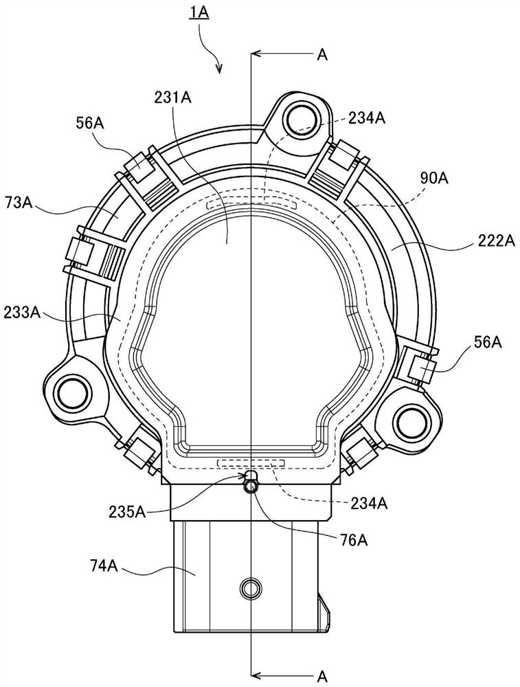
[0055] figure 2 It is a perspective view of a motor 1A according to a second embodiment of the present invention. image 3 is a plan view of the motor 1A. Figure 4 It is a longitudinal sectional view of the motor 1A. in addition, Figure 4 Yes image 3 The cross-sectional view at position A-A in .
[0056] This motor 1A is mounted in, for example, an automobile, and is used as a driving source for generating a driving force of a transmission device. However, the motor of the present invention can also be used for applications other than transmission devices. For example, the motor of the present invention can also be used as a drive source for other parts of an automobile such as an electric power steering device, a brake device, an engine cooling fan, or an oil pump. In addition, the motor of the present invention may be mounted on home appliances, OA equipment, medical equipment, etc., and generate various driving forces.
[0057] like Figure 4 As shown...
no. 3 Embodiment approach >
[0099]
[0100] Image 6 It is a perspective view of the motor 1B of 3rd Embodiment of this invention. Figure 7 It is a longitudinal sectional view of the motor 1B.
[0101] The motor 1B is mounted on, for example, an automobile, and is used as a driving source for generating a driving force of a braking device. However, the motor of the present invention can also be used for applications other than braking devices. For example, the motor of the present invention can also be used as a drive source for other parts of an automobile such as an electric power steering device, a transmission device, an engine cooling fan, or an oil pump. In addition, the motor of the present invention may be mounted on home appliances, OA equipment, medical equipment, etc., and generate various driving forces.
[0102] like Figure 7 As shown, the motor 1B has a stationary part 2B and a rotating part 3B. The stationary unit 2B is fixed to a housing of a device to be driven. The rotating pa...
PUM
 Abstract
Description
Claims
Application Information
 - R&D Engineer
- R&D Manager
- IP Professional
- Industry Leading Data Capabilities
- Powerful AI technology
- Patent DNA Extraction
Browse by: Latest US Patents, China's latest patents, Technical Efficacy Thesaurus, Application Domain, Technology Topic, Popular Technical Reports.
© 2024 PatSnap. All rights reserved.Legal|Privacy policy|Modern Slavery Act Transparency Statement|Sitemap|About US| Contact US: help@patsnap.com


