
Device for leg movement of ICU patients

A leg and activity technology, applied in pneumatic massage, transportation and packaging, passive exercise equipment, etc., can solve the problems of affecting recovery and normal walking, trouble, physical strength and time consumption, etc., to improve the effect of leg movement, operation The process is convenient and simple, and the effect of reducing labor intensity

Active Publication Date: 2021-04-02
溧阳市中医医院
View PDF8 Cites 2 Cited by
  • Summary
  • Abstract
  • Description
  • Claims
  • Application Information

AI Technical Summary

Problems solved by technology

[0002] ICU patients lie on the hospital bed and keep one posture for a long time (the supine posture is the majority). Because the patient cannot take care of himself and needs to stay in one posture for a long time, the patient lies down for a long time, which will easily affect the blood circulation of the patient's lower limbs, resulting in edema. Time inactivity will lead to atrophy of leg muscles and ligaments, and the internal function of the whole body will also deteriorate, which will also affect the later recovery and normal walking. At present, the nursing staff or the patient's family members usually hold the patient's leg with their hands and repeat the bending movement , and it takes a certain amount of time to be effective, but this requires the nursing staff to consume a lot of physical strength and time, and also requires the nursing staff to grasp the strength to avoid hurting the patient, so this method of artificially assisted movement is more troublesome and not enough Convenient, resulting in high labor intensity for medical staff or patients' families

Method used


Image

  • Device for leg movement of ICU patients
  • Device for leg movement of ICU patients
  • Device for leg movement of ICU patients

Examples


Embodiment Construction

[0022]Next, the technical solutions in the embodiments of the present invention will be apparent from the embodiment of the present invention, and it is clearly described, and it is understood that the described embodiments are merely embodiments of the present invention, not all of the embodiments.

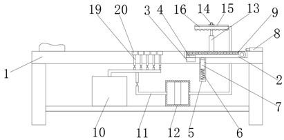
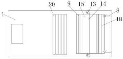
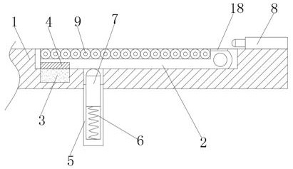
[0023]ReferFigure 1-5A device for the leg activity of the ICU patient, including the bed 1, and the upper end surface of the bed is adjacent to the bed at the end of the bed, the mounting tank is close to one end of the bed tail through the horizontal rotating shaft mounted a rotary plate 2 The mounting tank is embedded in the bottom surface of the mounting slot, which is embedded in a mounted electromagnet 3, and the lower end surface of the rotating plate 2 is embedded in a magnet block 4 attached to the electromagnet 3, the electromagnet 3 and magnet block 4. That is the same as one end magnetic pole, the upper end surface of the bed 1 is mounted at the bottom of the bed, and the first...


PUM


Abstract

The invention relates to the technical field of leg movement devices, in particular to a device for leg movement of ICU patients, which comprises a bed body, a mounting groove is formed in the position, close to the bed tail, of the upper end face of the bed body, a rotating plate is mounted at the end, close to the bed tail, of the mounting groove through a horizontal rotating shaft, an electromagnet is embedded in the end, close to the bed head, of the bottom face of the mounting groove, a magnet block matched with the electromagnet is embedded in the lower end face of the rotating plate, the magnetic poles of the close ends of the magnet block and the electromagnet are the same, two first electric telescopic rods corresponding to each other are mounted at the position, located at the bed tail, of the upper end face of the bed body, and the first electric telescopic rods are arranged along the length direction of the bed body. When the device is used, the electromagnet is set to workintermittently, so that the legs of a patient can move automatically, the operation process is convenient and easy, and the labor intensity of medical staff or family members of the patient is effectively reduced.

Description

Technical field[0001]The present invention relates to the technical field of leg movable devices, and more particularly to a device for leg activity for patients with ICU.Background technique[0002]ICU patient lying in the hospital bed for a long time to maintain a posture (mostly in the supine), because patients can't take care of themselves in a posture, the patient is lying for a long time, it is easy to affect the blood circulation of the lower limbs of the patient, thereby generating edema, due to long Time is inactive causes leg muscles, ligament atrophy, and the internal function of the whole body will also be deteriorated, and it will affect the post-recovery and normal walking. At present, the caregiver or the patient's family will continue to repeat the patient's legs. And it is necessary to have a certain amount of time, but this requires a lot of physical strength and time to consume a lot of physical strength, and the nursing staff will need to grasp the strength, avoid ...

Claims


Application Information

Patent Timeline
Patent Type & Authority Applications(China)
IPC IPC(8): A61H1/02A61H7/00A61H9/00A61G7/05A61G7/075
CPCA61H1/0237A61H7/00A61H9/005A61G7/05A61G7/0755A61H2201/0142A61H2201/0207A61H2201/025A61H2201/1207A61H2201/1642A61H2205/10A61G2210/30A61G2210/90
Inventor 高慧王建林
Owner 溧阳市中医医院
Learn More