Crushing and smelting equipment for plastic processing
A smelting equipment and plastic technology, which is applied in the field of crushing and smelting equipment for plastic processing, can solve the problems of cumbersome process and failure to teach crushing and smelting equipment well.
- Summary
- Abstract
- Description
- Claims
- Application Information
AI Technical Summary
Problems solved by technology
Method used
Image

Examples
specific Embodiment approach 1
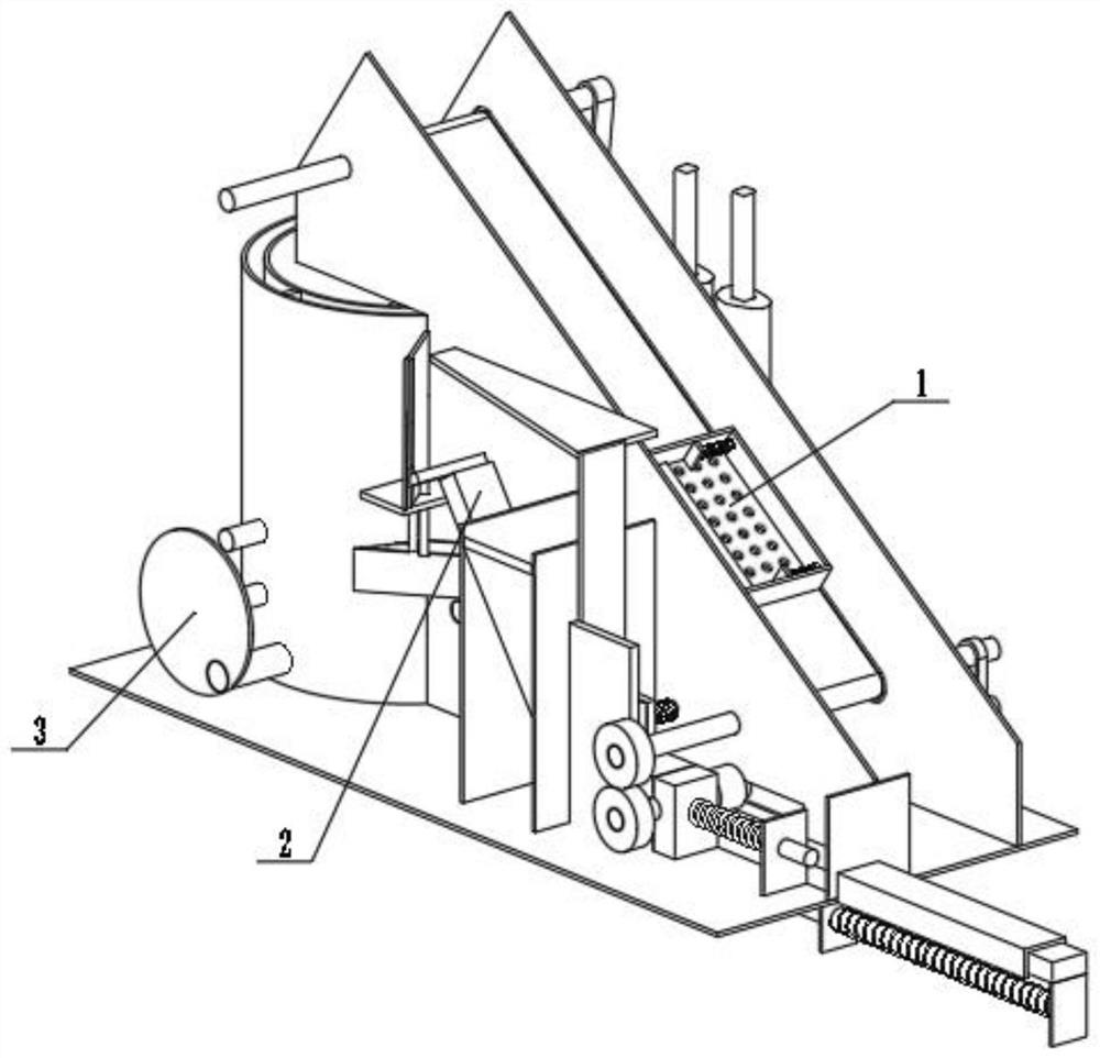
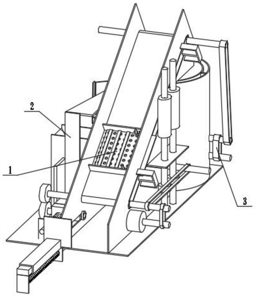
[0033] Combine below figure 1 , figure 2 , image 3 , Figure 4 , Figure 5 , Figure 6 , Figure 7 , Figure 8 , Figure 9 , Figure 10 , Figure 11 , Figure 12 , Figure 13 , Figure 14 , Figure 15 , Figure 16 , Figure 17 Describe this embodiment. The present invention relates to a sampling device, more specifically a crushing and smelting device for plastic processing, including a conveying and filtering mechanism 1, an automatic input mechanism 2, and a crushing and smelting mechanism 3. The equipment can process the The plastic is sent to the crushing barrel. The equipment can automatically transfer the smaller plastics to the melting barrel during the process of conveying the plastic to be processed. The equipment can crush the plastic sent to the crushing barrel and output it to the melting barrel. The equipment can The plastic in the melting barrel is smelted into liquid plastic and output to the equipment intermittently.
[0034] The conveying and...
specific Embodiment approach 2
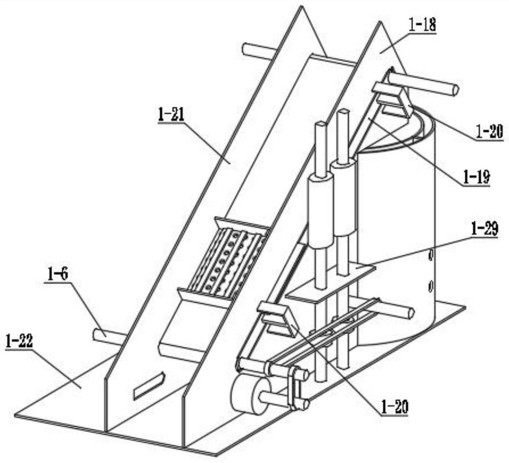
[0036] Combine below figure 1 , figure 2 , image 3 , Figure 4 , Figure 5 , Figure 6 , Figure 7 , Figure 8 , Figure 9 , Figure 10 , Figure 11 , Figure 12 , Figure 13 , Figure 14 , Figure 15 , Figure 16 , Figure 17 Describe this embodiment, this embodiment will further explain the first embodiment, the transmission filter mechanism 1 includes a motor 1-1, a motor shaft 1-2, a belt a1-3, a conveyor belt 1-4, and a leakage hole 1-5 , connecting shaft a1-6, belt b1-7, connecting shaft b1-8, friction wheel 1-9, connecting shaft c1-10, cam 1-11, sliding rubber soft plate 1-12, sliding plate limit plate 1- 13. Sliding limit spring 1-14, sliding plate limit plate a1-15, connecting plate a1-16, inclined output plate 1-17, connecting plate b1-18, bearing bar 1-19, bearing bar connecting block 1- 20. Connecting plate c1-21, connecting plate d1-22, output square hole 1-23, melting ring 1-24, connecting plate e1-25, crushing ring 1-26, crushing ring bottom pl...
specific Embodiment approach 3
[0038] Combine below figure 1 , figure 2 , image 3 , Figure 4 , Figure 5 , Figure 6 , Figure 7 , Figure 8 , Figure 9 , Figure 10 , Figure 11 , Figure 12 , Figure 13 , Figure 14 , Figure 15 , Figure 16 , Figure 17Describe this embodiment, this embodiment will further explain Embodiment 1, the automatic input mechanism 2 includes interlocking friction wheel a2-1, interlocking friction wheel b2-2, transmission shaft a2-3, interlocking friction wheel c2-4, Rubber friction strip 2-5, friction strip sliding groove 2-6, sliding groove installation plate 2-7, reset connection plate a2-8, reset shaft 2-9, return spring 2-10, reset connection plate b2-11, output Plate 2-12, feeding bar a2-13, feeding bar b2-14, pressing block 2-15, pressing connecting block 2-16, pushing shaft 2-17, pushing shaft chute 2-18, pushing connecting plate 2 -19, limit column 2-20, input groove 2-21, reciprocating compression block 2-22, reciprocating compression shaft 2-23, rec...
PUM
 Abstract
Description
Claims
Application Information
 - R&D
- Intellectual Property
- Life Sciences
- Materials
- Tech Scout
- Unparalleled Data Quality
- Higher Quality Content
- 60% Fewer Hallucinations
Browse by: Latest US Patents, China's latest patents, Technical Efficacy Thesaurus, Application Domain, Technology Topic, Popular Technical Reports.
© 2025 PatSnap. All rights reserved.Legal|Privacy policy|Modern Slavery Act Transparency Statement|Sitemap|About US| Contact US: help@patsnap.com