

Mattress magnetic particle mounting equipment
A technology for installing equipment and magnetic particles, applied in mattresses, spring mattresses, magnetic therapy, etc., can solve the problems of low long-term efficiency and insufficient installation effect, and achieve high installation efficiency, good hole opening effect, and high quality Effect
- Summary
- Abstract
- Description
- Claims
- Application Information
AI Technical Summary
Problems solved by technology
Method used
Image

Examples
Embodiment 1
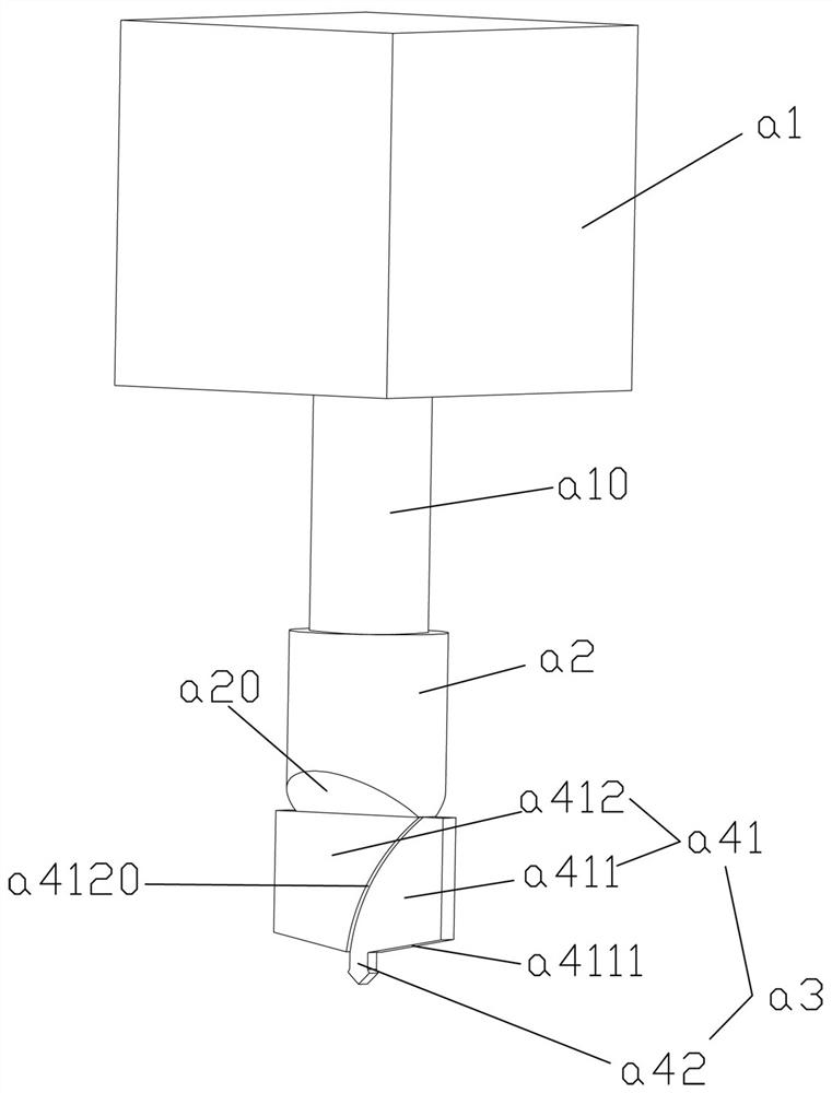
[0026] Example 1, such as Figure 1-7 As shown, a mattress punching cutter head includes a mounting column a2 for assembling with the motor shaft a10 of the punching rotary motor a1 and extending in the up and down direction, and the motor shaft a10 of the punching rotary motor a1 also extends in the up and down direction , the mounting column a2 can be connected with the pin shaft of the motor shaft a10, the cutter head is preferably made of carbon steel, of course, metal materials such as steel can also be used, and the bottom of the mounting column a2 is fixed with a blade a3 that rotates with the mounting column a2 The preferred body part of the mounting post a2 is a cylindrical structure, the lateral width of the blade a3 is preferably larger than the diameter of the mounting post a2 and the axis of the mounting post a2 preferably passes through the center of the width direction of the blade a3, and the blade a3 includes a The upright main body supporting cutting portion ...
Embodiment 2
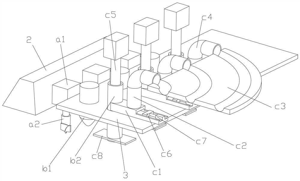
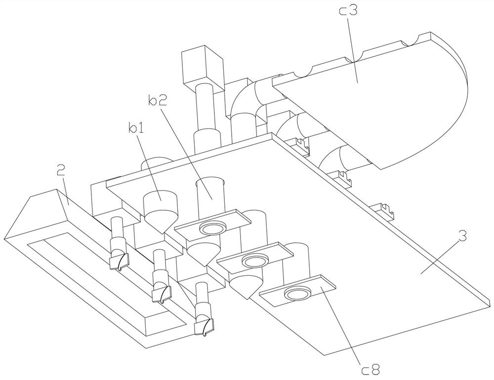
[0034] Example 2, such as Figure 1-7 As shown, a mattress magnetic particle conveying device includes a row of magnetic particle falling guide cylinders b2 arranged at intervals in the left and right directions and used for magnetic particles to fall into the holes of the flexible pad. The magnetic particle falling guide cylinder b2 is upright and is connected with a magnetic particle transverse conveying channel c1 extending forward, and the magnetic particle transverse conveying channel c1 is connected with an upright inlet channel c2, and the magnetic particles can continuously enter into the inlet channel c2 from above and can be piled up and down, and then The magnetic particles can be transported horizontally and horizontally through the horizontal conveying channel c1 of the magnetic particles, and can enter the magnetic particle falling guide cylinder b2, and the magnetic particle falling guide cylinder b2 can drop the magnetic particles into the hole of the flexible p...
Embodiment 3
[0042] Example 3, such as Figure 1-7 As shown, a mattress magnetic particle installation equipment includes a conveyor belt 1 and a mattress punching device for punching flexible pads that are sequentially arranged on the conveying path of the conveyor belt from back to front, for A hole dispensing device for applying glue to the flexible pad holes formed after the flexible pad is punched, and a mattress magnetic particle delivery device for filling magnetic particles into the holes of the flexible pad. The mattress punching device It has a row of mattress punching cutter heads arranged at intervals in the left and right directions and is used to rotate and punch holes in the flexible pad. Cylinder b1, the mattress magnetic particle conveying device has a row of magnetic particle falling guide cylinders b2 arranged at intervals in the left and right directions and used for magnetic particles to fall into the holes of the flexible pad.
[0043] Preferably, a dust suction devi...
PUM
 Abstract
Description
Claims
Application Information