Supercharge Your Innovation With Domain-Expert AI Agents!

Automatic drainage system and method for compressed air pipeline

A technology of compressed air pipes and automatic drainage, which is applied in pipeline systems, gas/liquid distribution and storage, mechanical equipment, etc. It can solve the problems of untimely drainage, troublesome operation, and increased workload of staff, so as to reduce labor intensity, Convenient control and timely operation

Inactive Publication Date: 2021-04-02
CRRC MEISHAN
View PDF8 Cites 0 Cited by
  • Summary
  • Abstract
  • Description
  • Claims
  • Application Information

AI Technical Summary

Problems solved by technology

The manual drainage operation is more troublesome, which increases the workload of the staff
Moreover, parameters such as drainage pressure and drainage time are difficult to accurately control, resulting in problems such as untimely drainage.

Method used


Image

  • Automatic drainage system and method for compressed air pipeline
  • Automatic drainage system and method for compressed air pipeline

Examples


Embodiment 1

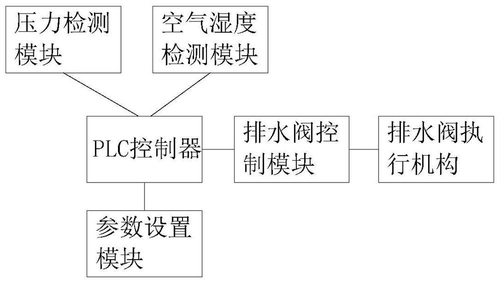
[0023] Such as figure 1 As shown, the compressed air pipeline automatic drainage system of this embodiment includes a PLC controller, the PLC controller is electrically connected to a drainage control module, and the drainage control module is electrically connected to a drainage valve installed at the outlet of the buffer tank of the compressed air pipeline, The PLC controller is electrically connected with a pressure detection module, an air humidity detection module and a parameter setting module respectively, and the parameter setting module is used to set the drainage time of the drainage valve, the drainage pressure of the drainage valve, and the drainage waiting time.

[0024] The pressure detection module can detect the pressure of the compressed air, and the air humidity detection module can detect the humidity of the compressed air. The parameter setting module can set parameters such as the drainage time of the drainage valve, the drainage pressure of the drainage v...

Embodiment 2

[0028] A method for automatic drainage of compressed air pipelines, comprising the steps of:

[0029] S1: According to the parameters including air humidity and compressed air pressure, set the drain valve drain time, drain valve drain pressure, and drain waiting time in the DCS system;

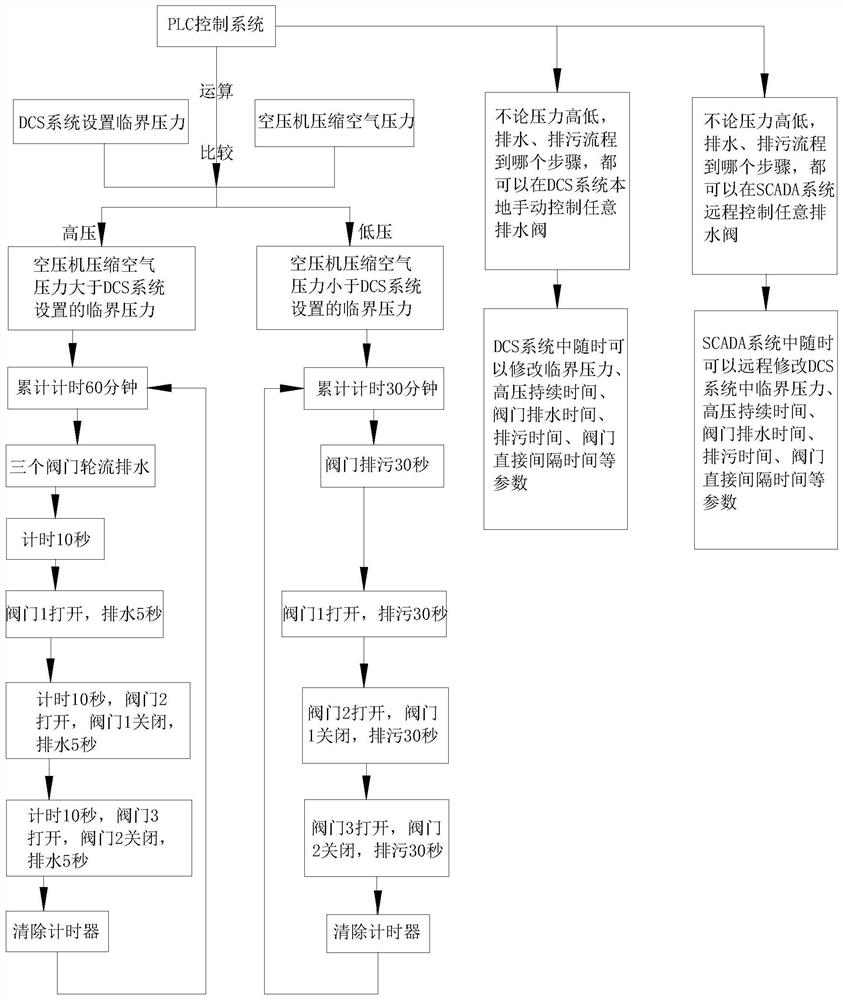
[0030] Among them, such as figure 2 As shown, when setting the drainage time of the drainage valve, the drainage pressure of the drainage valve, and the waiting time of the drainage valve in the DCS system, when the compressed air pressure is lower than the critical pressure of the drainage valve, the drainage valve is in the sewage discharge state. When the setting exceeds 30 minutes in total, 3 The valves take turns to discharge sewage for 30 seconds, and then restart the counting work; when the pressure is higher than the critical pressure of the drain valve, the drain valve is in the draining state. After setting the cumulative pressure to maintain the state for 1 hour, the three valves ...


PUM


Abstract

The invention belongs to the technical field of air compression devices, and particularly relates to an automatic drainage system and method for a compressed air pipeline. According to the technical scheme, the automatic drainage system for the compressed air pipeline comprises a PLC, the PLC is electrically connected with a drainage control module, the drainage control module is electrically connected with a drainage valve installed at an outlet of a buffer tank of the compressed air pipeline, the PLC is electrically connected with a pressure detection module, an air humidity detection moduleand a parameter setting module, and the parameter setting module is used for setting the drainage time, the drainage pressure and the drainage waiting time of the drainage valve. According to the automatic drainage system and method for the compressed pipeline, drainage parameters can be set for automatic drainage.

Description

technical field [0001] The invention belongs to the technical field of air compression devices, and in particular relates to an automatic drainage system and method for compressed air pipelines. Background technique [0002] In some enterprises, compressed air is an important source of power. In some southern cities, the water vapor in the air is relatively heavy, and the buffer tank of compressed air needs regular artificial drainage. The manual drainage operation is more troublesome and increases the workload of the staff. Moreover, parameters such as drainage pressure and drainage time are difficult to accurately control, resulting in problems such as untimely drainage. Contents of the invention [0003] In order to solve the above-mentioned problems in the prior art, the purpose of the present invention is to provide an automatic drainage system and method for compressed pipelines that can set drainage parameters for automatic drainage. [0004] The technical scheme ...

Claims


Application Information

Patent Timeline
IPC IPC(8): F17D1/02F17D3/01F17D3/14
CPCF17D1/02F17D3/01F17D3/145
Inventor 刘亚军潘伟谢文军宇文卧龙张晋华龙东旭
Owner CRRC MEISHAN
Features
  • R&D
  • Intellectual Property
  • Life Sciences
  • Materials
  • Tech Scout
  • Unparalleled Data Quality
  • Higher Quality Content
  • 60% Fewer Hallucinations
Learn More