Kitchen air conditioner structure and kitchen air conditioner
A kitchen and air-conditioning technology, which is applied in the field of kitchen air-conditioning structure and kitchen air-conditioning, can solve the problems of inconvenient installation of the external unit of the split unit, difficulty in air-conditioning pipe routing, and narrow space, and achieves small space occupation, wide air outlet range, The effect of compact distribution
- Summary
- Abstract
- Description
- Claims
- Application Information
AI Technical Summary
Problems solved by technology
Method used
Image

Examples
Embodiment 1
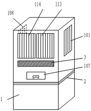
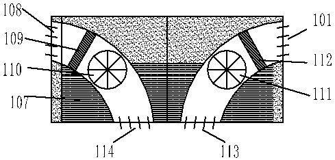
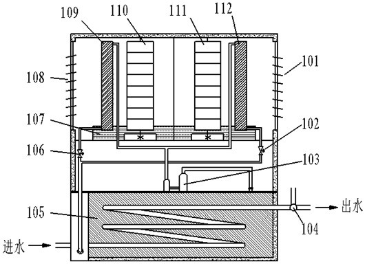
[0042] A kitchen air-conditioning structure, such as figure 1 and image 3 As shown, it includes a body 1, the body 1 includes an upper part and a lower part, and the upper part and the lower part are of an integrated structure. The middle part of the body 1 is provided with a partition 2, the upper side of the body 1 is provided with symmetrically arranged side air inlet 1 101 and side air inlet 2 108, and the front side of the upper part of the body 1 is provided with symmetrically distributed air outlets. Air outlet 1 113 and air outlet 2 114, the body 1 is provided with an evaporator, cross-flow fan 1 111 and cross-flow fan 2 110, the evaporator and cross-flow fan are located between the corresponding side air inlet and air outlet inside the air duct;
[0043] Such as figure 1 and image 3 As shown, the front side of the body 1 is provided with a touch control panel 3 and a water collection tank 107; the body 1 is provided with a compressor 103, and the lower part of t...
Embodiment 2
[0053] A kitchen air-conditioning structure, such as figure 1 and image 3 As shown, it includes a body 1, the body 1 includes an upper part and a lower part, and the upper part and the lower part are of an integrated structure. The middle part of the body 1 is provided with a partition 2, the upper side of the body 1 is provided with symmetrically arranged side air inlet 1 101 and side air inlet 2 108, and the front side of the upper part of the body 1 is provided with symmetrically distributed air outlets. Air outlet one 113 and air outlet two 114, the body 1 is provided with an evaporator, cross-flow fan one 111 and cross-flow fan two 110, the evaporator and cross-flow fan are located between the corresponding side air inlet and air outlet inside the air duct;
[0054] Such as figure 1 and image 3 As shown, the front side of the body 1 is provided with a touch control panel 3 and a water collection tank 107; the body 1 is provided with a compressor 103, and the lower p...
Embodiment 3
[0059] A kitchen air-conditioning structure, such as figure 1 and image 3 As shown, it includes a body 1, the body 1 includes an upper part and a lower part, and the upper part and the lower part are of an integrated structure. The middle part of the body 1 is provided with a partition 2, the upper side of the body 1 is provided with symmetrically arranged side air inlet 1 101 and side air inlet 2 108, and the front side of the upper part of the body 1 is provided with symmetrically distributed air outlets. Air outlet one 113 and air outlet two 114, the body 1 is provided with an evaporator, cross-flow fan one 111 and cross-flow fan two 110, the evaporator and cross-flow fan are located between the corresponding side air inlet and air outlet inside the air duct;
[0060] Such as figure 1 and image 3 As shown, the front side of the body 1 is provided with a touch control panel 3 and a water collection tank 107; the body 1 is provided with a compressor 103, and the lower p...
PUM
 Abstract
Description
Claims
Application Information
 - R&D
- Intellectual Property
- Life Sciences
- Materials
- Tech Scout
- Unparalleled Data Quality
- Higher Quality Content
- 60% Fewer Hallucinations
Browse by: Latest US Patents, China's latest patents, Technical Efficacy Thesaurus, Application Domain, Technology Topic, Popular Technical Reports.
© 2025 PatSnap. All rights reserved.Legal|Privacy policy|Modern Slavery Act Transparency Statement|Sitemap|About US| Contact US: help@patsnap.com