Ice and frost removing device and ice and frost removing method

A frost and shell technology, applied in the field of oil production pipeline treatment, can solve the problems of easy damage to the surface of the casing head, damage to the surface of the oil rod thread, time-consuming and labor-intensive steel brazing, etc., to achieve good melting effect, avoid secondary condensation, The effect of fast defrosting speed

Active Publication Date: 2021-04-02
PETROCHINA CO LTD
View PDF6 Cites 0 Cited by
  • Summary
  • Abstract
  • Description
  • Claims
  • Application Information

AI Technical Summary

Problems solved by technology

[0007] The object of the present invention is to overcome above-mentioned deficiencies in the prior art, provide a kind of deicing device and deicing method, have overcome 1 in the prior art: use steel wire brush to scrub oil rod screw thread, both time-consuming and laborious, moreover frost hardness is relatively high. High, it is difficult to brush it off with a s

Method used


Image

  • Ice and frost removing device and ice and frost removing method
  • Ice and frost removing device and ice and frost removing method
  • Ice and frost removing device and ice and frost removing method

Examples


specific Embodiment approach

[0039] It should be noted that the structures, proportions, sizes, etc. shown in this specification are only used to cooperate with the content disclosed in the specification for the understanding and reading of those familiar with this technology, and are not used to limit the conditions for the implementation of the present invention , any modification of structure, change of proportional relationship or adjustment of size shall still fall within the scope covered by the technical content disclosed in the present invention without affecting the effect and purpose of the present invention. .

[0040] At the same time, terms such as "upper", "lower", "left", "right", "middle" and "one" quoted in this specification are only for the convenience of description and are not used to limit this specification. The practicable scope of the invention and the change or adjustment of its relative relationship shall also be regarded as the practicable scope of the present invention without...

Embodiment 1

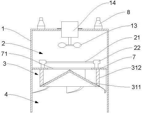
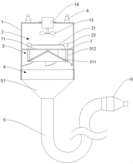
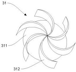
[0044] Such as figure 1 As shown, the present invention discloses a deicer, which includes a housing 1, wherein a heating chamber 2, a diversion chamber 3 and a drying chamber 4 are sequentially arranged in the housing 1, wherein the heating chamber 2, the diversion chamber 3 and the The drying chamber 4 runs through in sequence, and the heating chamber 2 is provided with a heating element and an air supply element, wherein the air supply element is arranged on the side of the heating chamber 2 away from the diversion chamber 3, and the heating element is arranged in the heating chamber 2 One side close to the diversion chamber 3, wherein the heating element and the air supply element are respectively connected to an external power supply through a cable, and the diversion chamber 3 is provided with a diversion element 31, wherein the diversion element 31 is used to pass through the diversion chamber The air flow of 3 turns into a spiral air flow, and one end of the drying cha...

Embodiment 2

[0046] Such as figure 1 As shown, the present invention discloses a deicer, which includes a housing 1, wherein a heating chamber 2, a diversion chamber 3 and a drying chamber 4 are sequentially arranged in the housing 1, wherein the heating chamber 2, the diversion chamber 3 and the The drying chamber 4 runs through in sequence, and the heating chamber 2 is provided with a heating element and an air supply element, wherein the air supply element is arranged on the side of the heating chamber 2 away from the diversion chamber 3, and the heating element is arranged in the heating chamber 2 One side close to the diversion chamber 3, wherein the heating element and the air supply element are respectively connected to an external power supply through a cable, and the diversion chamber 3 is provided with a diversion element 31, wherein the diversion element 31 is used to pass through the diversion chamber The air flow of 3 turns into a spiral air flow, and one end of the drying cha...


PUM


Abstract

The invention discloses an ice and frost removing device and an ice and frost removing method. The device comprises a shell, a heating chamber, a flow guide chamber and a drying chamber are sequentially arranged in the shell, the heating chamber, the flow guide chamber and the drying chamber sequentially communicate, a heating element and an air supply element are arranged in the heating chamber,the air supply element is arranged on the side, away from the flow guide chamber, in the heating chamber, the heating element is arranged on the side, close to the flow guide chamber, in the heating chamber, the heating element and the air supply element are externally connected with a power supply through cables respectively, a flow guide element is arranged in the flow guide chamber and used forchanging airflow passing through the flow guide chamber into spiral airflow, an opening is formed in one end of the drying chamber, the opening of the drying chamber is used for placing an iced and frosted tubing head or oil rod screw thread, and the diameter of the opening end of the drying chamber is larger than the outer diameter of the tubing head or oil rod screw thread.

Description

technical field [0001] The invention belongs to the technical field of oil production pipeline treatment, and in particular relates to a de-icing device and a de-icing method. Background technique [0002] In the maintenance and repair process of underground operations in oil exploitation, due to the low temperature in severe winter, the oil pipe rods placed on the ground must be cleaned of wax by the boiler car before entering the well, and the threads will freeze after the wax is removed; or logging in the oil production well When the gas condenses in the casing, condensate oil is produced, and water is brought out at the same time, so that the casing head of the test well freezes, causing the casing to be blocked by ice during well logging and unable to perform well logging. [0003] The conventional deicing and defrosting methods currently adopted are: [0004] Brush the oil rod screw thread after the boiler car thorn washing with a wire brush in turn to clean the frost...

Claims


Application Information

Patent Timeline
IPC IPC(8): F25D21/08F25D21/14
CPCF25D21/08F25D21/14
Inventor 赵旭东秦大鹏丑建勋王宇超杜爱华陈善琴梁鹏陈亮袁斌辛胜杰洪亮彭章保鲁晓斌魏波谢晓川杨飞安小虎孙燕刘振宁刘丽娜黄延明黄发勇刘军峰金婷刘涛马斌戴宝铭李晨史冠楠
Owner PETROCHINA CO LTD
Why Eureka
Try Eureka