
Super-large field-of-view polarization camera based on bionic curved compound eye

A curved compound eye and field of view technology, which is applied in the direction of measuring the polarization of light, measuring devices, instruments, etc., which can solve the problem that the position information, intensity information and target material information of the target cannot be accurately obtained, the polarization imaging system is complicated, and the imaging range is small, etc. It can achieve the effect of high-resolution reconstruction of images, less difficulty in assembly and maintenance, and improved accuracy and reliability.

Active Publication Date: 2021-04-02
XI'AN INST OF OPTICS & FINE MECHANICS - CHINESE ACAD OF SCI
View PDF6 Cites 1 Cited by
  • Summary
  • Abstract
  • Description
  • Claims
  • Application Information

AI Technical Summary

Problems solved by technology

[0005] The purpose of the present invention is to solve the problems that the existing polarization imaging system is complex, difficult to install and adjust, the imaging range is small, and the position information, intensity information and target material information of the target cannot be accurately obtained. Field polarization camera for large field of view polarization imaging

Method used


Image

  • Super-large field-of-view polarization camera based on bionic curved compound eye
  • Super-large field-of-view polarization camera based on bionic curved compound eye
  • Super-large field-of-view polarization camera based on bionic curved compound eye

Examples


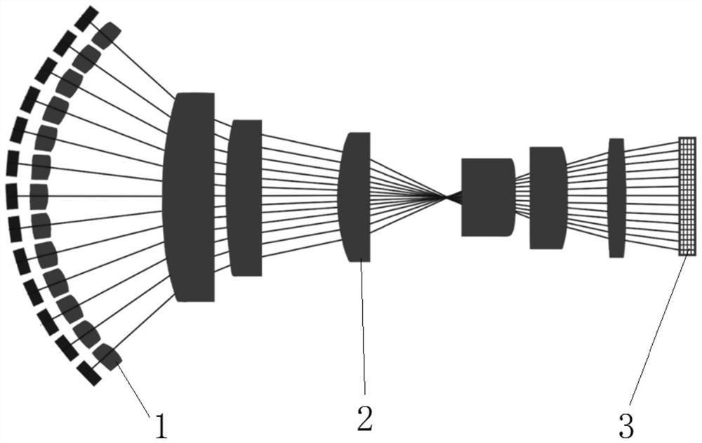
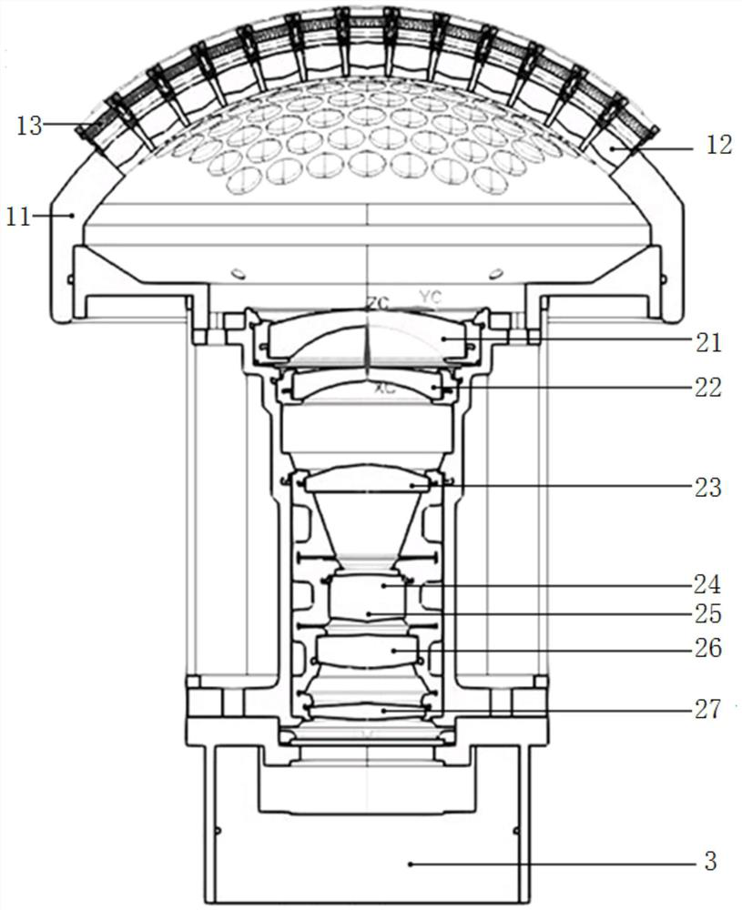
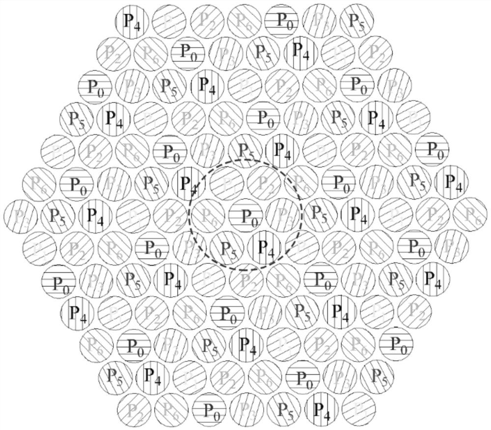
Embodiment Construction

[0027] The present invention will be described in further detail below in conjunction with the accompanying drawings and specific embodiments.

[0028] The invention provides a super large field of view polarization camera based on a bionic curved surface compound eye. The super large field of view polarization camera is inspired by the structure of biological compound eyes in nature, and the sub-lenses are arranged into a curved surface to obtain scene information of a large field of view. Polarization information within the range, the polarizers are diffused to the entire aperture array in a hexagonal arrangement, and the polarization image of the scene with a large field of view can be extracted by cooperating with the existing algorithm. The super large field of view polarization camera of the present invention can obtain a super large field of view The polarization image information of the scene, the polarization information can effectively improve the contrast between tar...


PUM

PropertyMeasurementUnit
Optical lengthaaaaaaaaaa

Abstract

The invention provides a super-large field-of-view polarization camera based on a bionic curved surface compound eye. The problems that an existing polarization imaging system is complex in structure,large in installation and adjustment difficulty and small in imaging range, and position information, intensity information and target material information of a target cannot be accurately obtained are solved. The camera comprises a curved-surface compound eye unit, an optical relay image transferring subunit and a large-area-array plane detector which are arranged in sequence, wherein the curved-surface compound eye unit comprises a supporting shell, a sub-lens array and a polarizing film array; a plurality of mounting holes are formed in the surface of the supporting shell; the sub-lens array comprises a plurality of curved-surface sub-lenses, and the curved-surface sub-lenses are arranged from the center to the periphery in a hexagonal mode; the polarizing film array comprises a plurality of polarizing films, and the polarizing films are located on an incident light path of the curved-surface sub-lens; the optical relay image transferring subunit is used for guiding the curved-surface image information acquired by the curved-surface compound eye unit to the large-area-array plane detector; and the large-area-array plane detector is used for collecting image information in different polarization directions.

Description

technical field [0001] The invention belongs to the field of polarization optical imaging system design and photoelectric detection, and in particular relates to a super large field of view polarization camera based on a bionic curved surface compound eye. Background technique [0002] Polarization imaging technology can comprehensively obtain multi-dimensional features such as target polarization and images by collecting electromagnetic wave information radiated or reflected by the target, effectively enhance the contrast between images, highlight the detailed features of the target, and improve the ability of target detection and recognition. [0003] At present, the main polarization imaging detection methods can be divided into four types: time-divided, amplitude-divided, aperture-divided and focal-plane-divided. The time-sharing polarization imaging system obtains all the polarization components of the target light wave by manually or electrically rotating the polarizer...

Claims


Application Information

Patent Timeline
IPC IPC(8): G01J4/00G02B27/28G02B3/00
CPCG01J4/00G02B27/28G02B3/0006G01J4/04
Inventor 鱼卫星许黄蓉武登山张远杰胡炳樑
Owner XI'AN INST OF OPTICS & FINE MECHANICS - CHINESE ACAD OF SCI
Learn More