
Sine wave waveform combined compensation method for arresting impact test

A compensation method and impact test technology, which is applied in the direction of impact test, machine/structural component test, measuring device, etc., can solve the problems of under-testing of products, waste of test resources, low actual test value, etc., and achieve simple parameter determination, Avoid Tried Effects

Active Publication Date: 2021-04-02
CHINESE AERONAUTICAL RADIO ELECTRONICS RES INST
View PDF10 Cites 0 Cited by
  • Summary
  • Abstract
  • Description
  • Claims
  • Application Information

AI Technical Summary

Problems solved by technology

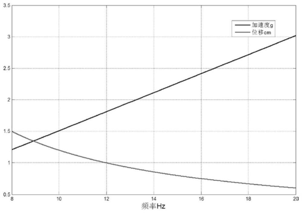
The impact load at the moment of the arresting landing and the forced braking load of the arresting cable are quite different from those of the ordinary landing, but the test value during the arresting landing process is higher, the duration is longer than the general impact test, and the requirements for the shaking table are higher. If the original arresting shock test waveform is directly used in the product verification process in the laboratory, the acceleration, velocity and displacement curves of the shaking table are as follows: figure 1 , the displacement can reach 900mm. At present, neither the traditional mechanical hydraulic vibration table nor the electromagnetic vibration table can directly carry out the arresting impact test with the original test curve.
[0003] At present, most shaking tables usually use high-pass filtering to process the original curve in this test. This method has two main limitations: 1. After high-pass filtering, part of the high-frequency signal is removed, and the actual test value is lower than the standard requirement, resulting in The actual product is under test
2. The actual vibration balance position of the shaking table during the test process cannot be changed through high-pass filtering, resulting in a waste of actual test resources on the shaking table, and it is difficult to cope with higher-value tests

Method used


Image

  • Sine wave waveform combined compensation method for arresting impact test
  • Sine wave waveform combined compensation method for arresting impact test
  • Sine wave waveform combined compensation method for arresting impact test

Examples


Embodiment Construction

[0027] The present invention will be further described in detail below in conjunction with the accompanying drawings and embodiments.

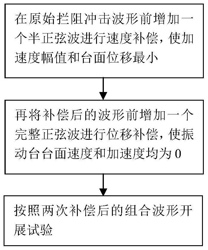
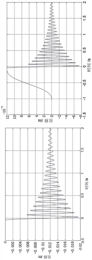
[0028] see Figure 4 As shown, a sine wave waveform combination compensation method for the arresting impact test shown in this embodiment is applied on a shaking table, and a half-period sine wave and a full-period sine wave are loaded before the test waveform on the velocity and The displacement is compensated, in which the speed compensation is performed by adding a half-period sine wave, and the displacement compensation is performed by adding a full-period sine wave. By controlling the wave frequency and amplitude of the compensated sine wave, the displacement and velocity are within the limits of the parameters of the shaking table. The specific compensation process is as follows:

[0029] Step 1: Add a half sine wave before the original arresting shock waveform for speed compensation. The parameters of the half sine wave are as follow...


PUM


Abstract

The invention discloses a sine wave waveform combined compensation method for an arresting impact test, which is characterized by comprising the steps of 1, adding a half-sine wave in front of an original arresting impact waveform to perform speed compensation so as to enable the acceleration amplitude and the table top displacement to be the minimum; 2, adding a complete sine wave in front of thecompensated waveform to perform displacement compensation so as to enable the speed and the acceleration of the table top of the vibration table to be both 0; and 3, carrying out a test according tothe combined waveform after two times of compensation. According to the invention, an arresting impact test can be carried out on part of vibration tables whose speed and displacement do not meet testconditions.

Description

technical field [0001] The invention relates to a sine wave waveform combination compensating method for arresting impact test, which can make the arresting impact test be carried out on a vibrating table whose partial speed and displacement do not meet the test conditions. Background technique [0002] The product needs to be able to work normally under the overload of itself and the external environment, which requires the product to be verified by testing equipment in the laboratory. The arresting landing process is completely different from the landing approach of ordinary aircraft. The aircraft must land on the calibrated glide path, and the aircraft must be decelerated and braked in a short distance by the landing brake arresting cable. The impact load at the moment of the arresting landing and the forced braking load of the arresting cable are quite different from those of the ordinary landing, but the test value during the arresting landing process is higher, the dur...

Claims


Application Information

Patent Timeline
IPC IPC(8): G01M7/08
CPCG01M7/08
Inventor 周宏伟李晓文王狄辉
Owner CHINESE AERONAUTICAL RADIO ELECTRONICS RES INST
Learn More