Check patentability & draft patents in minutes with Patsnap Eureka AI!

Line contact friction testing machine with pressure scanning function, and pressure detection method

A friction testing machine, line contact technology, applied in the direction of measuring fluid pressure, measuring device, adopting mechanical device, etc.

Pending Publication Date: 2021-04-02
BEIJING INSTITUTE OF TECHNOLOGYGY
View PDF0 Cites 0 Cited by
  • Summary
  • Abstract
  • Description
  • Claims
  • Application Information

AI Technical Summary

Problems solved by technology

[0003] In order to further study the mechanism of cavitation and gushing phenomena in the friction process, it is necessary to detect the pressure distribution in the lubricating oil film in the friction area, but there is no equipment for detecting the pressure distribution in the lubricating oil film in the prior art

Method used


Image

  • Line contact friction testing machine with pressure scanning function, and pressure detection method
  • Line contact friction testing machine with pressure scanning function, and pressure detection method
  • Line contact friction testing machine with pressure scanning function, and pressure detection method

Examples


Embodiment 1

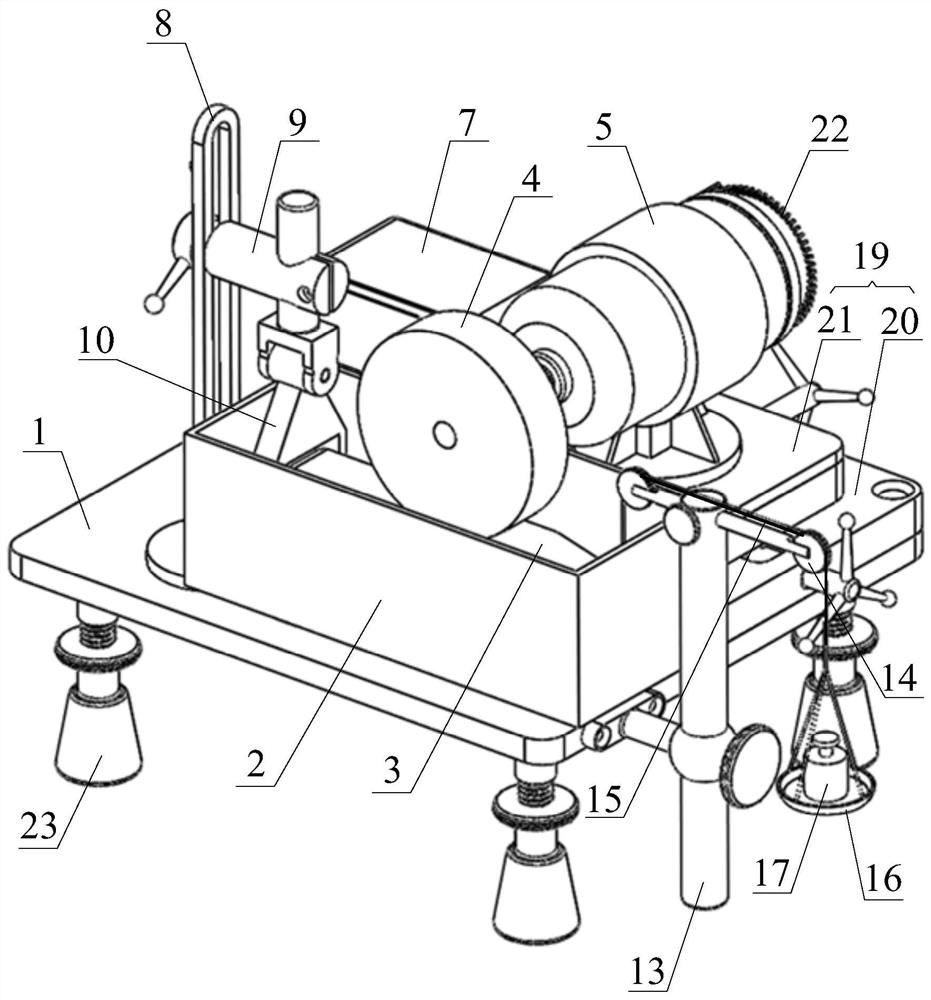
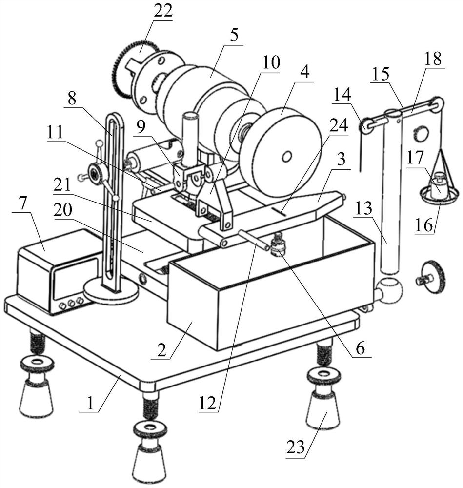
[0053] This embodiment provides a line contact friction testing machine with pressure scanning function, such as figure 1 and figure 2 As shown in the structure, the line contact friction testing machine includes a base 1, a lubricating oil tank 2, a friction plate 3, a friction disc 4, a driving motor 5, a hanger, a loading mechanism and a pressure sensor 6;

[0054] A lubricating oil tank 2 is installed on the top of the base 1; the base 1 is used as the installation basis of the line contact friction testing machine; in order to facilitate the adjustment of the base 1, multiple height-adjustable support feet can also be installed on the top of the base 1 23, at figure 1 and figure 2 The four corners of the bottom of the base are respectively provided with a supporting foot 23, and the height adjustment of the supporting foot 23 can be realized by threads;

[0055] Lubricating oil groove 2 is a groove structure with an open top, and lubricating oil and friction plate 3 ...

Embodiment 2

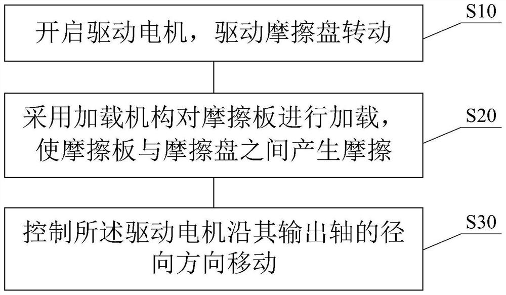
[0071] This embodiment provides a method for detecting the pressure distribution in the lubricating oil film. When detecting the internal pressure of the lubricating oil film, the line contact friction testing machine provided by the above embodiment is used. Refer to image 3 , the detection method includes the following steps:

[0072] Step S10, turn on the drive motor 5 to drive the friction disc 4 to rotate;

[0073] Step S20, using a loading mechanism to load the friction plate 3 to cause friction between the friction plate 3 and the friction disc 4;

[0074] Step S30, controlling the drive motor 5 to move along the radial direction of its output shaft.

[0075] The line contact friction between the friction disc 4 and the friction plate 3 can be realized by using the above-mentioned line contact friction testing machine, and the friction disc 4 is controlled to reciprocate relative to the friction plate 3 while friction occurs between the friction disc 4 and the frictio...


PUM


Abstract

The invention discloses a line contact friction testing machine with a pressure scanning function, and a pressure detection method. The linear contact friction testing machine is characterized in thata lubricating oil groove is formed in the top of a base; a hanging bracket and a loading mechanism are oppositely arranged at the two ends of the lubricating oil groove and fixedly installed on the base; a driving motor is mounted at the top of the base in a position-adjustable manner, and a friction disc is fixedly mounted at the end part of an output shaft of the driving motor; a friction plateis hoisted in the lubricating oil groove through the hanging bracket and the loading mechanism, is soaked in lubricating oil and is provided with a detection gap; constant linear contact friction isformed between the outer peripheral surface of the friction disc and the top surface of the friction plate; the loading mechanism is used for adjusting the contact pressure between the friction plateand the friction disc; and a pressure sensor is fixedly installed on the friction plate and is opposite to the detection gap. The line contact friction testing machine can detect the pressure distribution in the lubricating oil film in the contact friction area.

Description

technical field [0001] The invention relates to the technical field of friction, in particular to a line contact friction testing machine with a pressure scanning function and a pressure detection method. Background technique [0002] When an object and another object move along the tangential direction of the contact surface or have a friction tendency of relative motion, there will be an acting force between the contact surfaces of the two objects that hinders their relative motion. This force is called friction. This phenomenon or characteristic between contact surfaces is called "friction". Friction is both beneficial and harmful, but in most cases it is unfavorable. For example, friction during machine operation causes useless loss of energy and shortens the life of the machine, and reduces mechanical efficiency. Various measures are often adopted in the prior art to reduce friction, such as adding lubricating oil to the machine. When there is a low pressure area in t...

Claims


Application Information

Patent Timeline
Patent Type & Authority Applications(China)
IPC IPC(8): G01N19/02G01L11/00
CPCG01L11/00G01N19/02
Inventor 斯杰里马赫·亚历山大张昊付洪宇孙柏刚
Owner BEIJING INSTITUTE OF TECHNOLOGYGY
Features
  • R&D
  • Intellectual Property
  • Life Sciences
  • Materials
  • Tech Scout
  • Unparalleled Data Quality
  • Higher Quality Content
  • 60% Fewer Hallucinations
Learn More