Multi-axis synchronous control method and control system

A technology of multi-axis synchronization and control method, applied in general control system, control/regulation system, digital control and other directions, which can solve the problems of shortening the uniform distance and unable to guarantee the elongation of the lifting structure.

Pending Publication Date: 2021-04-02
中物智建(武汉)科技有限公司
View PDF7 Cites 0 Cited by
  • Summary
  • Abstract
  • Description
  • Claims
  • Application Information

AI Technical Summary

Problems solved by technology

[0005] The purpose of the present invention is to overcome the above-mentioned technical deficiencies, and propose a multi-axis synchronous control method and control system to solve the problem that if the center of gravity of the industrial equipment installed on the adjustment device is It is not fixed. For example, when the industrial mechanical arm is working, the simple synchronous power-on and power-off control does not guarantee that each lifting structure can be extended or shortened by a uniform distance.

Method used


Image

  • Multi-axis synchronous control method and control system
  • Multi-axis synchronous control method and control system
  • Multi-axis synchronous control method and control system

Examples


Embodiment Construction

[0033] In order to make the object, technical solution and advantages of the present invention clearer, the present invention will be further described in detail below in conjunction with the accompanying drawings and embodiments. It should be understood that the specific embodiments described here are only used to explain the present invention, not to limit the present invention.

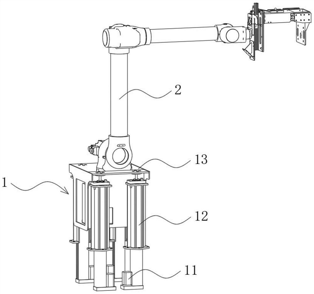
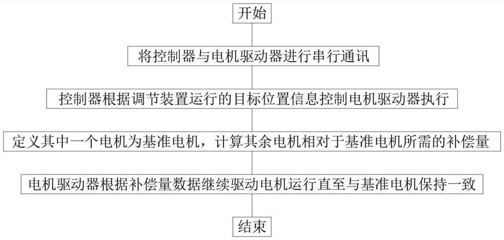
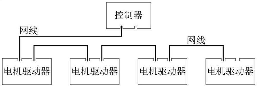
[0034] See Figure 1-5 , figure 1 It is a structural schematic diagram of a multi-axis synchronous control method and a control system provided by the present invention. figure 2 yes figure 1 Schematic diagram of the steps in the provided multi-axis synchronous control method. image 3 yes figure 1 The connection schematic diagram of the serial communication between the controller and the motor driver in the provided multi-axis synchronous control method. Figure 4 yes figure 1 Schematic diagram of the module structure in the multi-axis synchronous control system provided. Figure 5 It is a...


PUM


Abstract

The invention discloses a multi-axis synchronous control method and system, and the system comprises an adjustment device which comprises a plurality of motors and a lifting structure, and the methodcomprises the following steps that a controller carries out the serial communication with a plurality of motor drivers, the controller and the motor drivers carry out the data exchange through an Ethercat communication protocol, and the controller records the current encoder values of the plurality of motors and records the current encoder values as initial positions; and the controller obtains the target height needing to be adjusted by an adjusting device and transmits information into the controller, and the controller obtains a corresponding control command through calculation, converts the command into a motion command and transmits the motion command to the motor drivers to be executed. Compared with the prior art, all the lifting structures can be controlled to be always kept synchronous in real time according to the movement distance of each lifting structure, so that industrial equipment mounted on the adjusting device can be lifted in parallel when gravity center movement occurs, and the plane angle of the industrial equipment is kept unchanged; therefore, the industrial equipment can obtain a stable reference coordinate system.

Description

technical field [0001] The invention relates to the technical field of mechanical control, in particular to a multi-axis synchronous control method and a control system. Background technique [0002] In many industrial equipment, in order to increase the range of use of industrial equipment, an adjustment device is often added to the base of the industrial equipment. When the industrial equipment reaches the limit range but the distance is still not enough, the operating range of the industrial equipment can be increased by controlling the adjustment device. For example, installing the industrial robot arm on a liftable adjustment device can expand the working range of the industrial robot arm in the vertical direction. [0003] Existing adjustment devices are mainly divided into manual lift type, push rod type and single motor type. The manual lifting type is adjusted by manually turning the handwheel, which lacks automation. The push rod type is adjusted by controlling th...

Claims


Application Information

Patent Timeline
IPC IPC(8): G05B19/19
CPCG05B19/19G05B2219/35349
Inventor 张柏松余硕
Owner 中物智建(武汉)科技有限公司
Why Eureka
Try Eureka