Detachable and reusable module and loading and unloading method
A module and cell technology, applied in battery pack parts, electrical components, circuits, etc., can solve the problem of module and cell waste, and achieve the effect of saving replacement costs, simple operation, and tight connections
- Summary
- Abstract
- Description
- Claims
- Application Information
AI Technical Summary
Problems solved by technology
Method used
Image

Examples
Embodiment 1
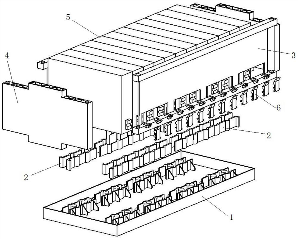
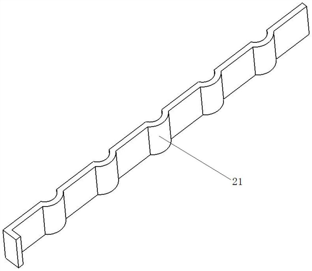
[0043] Such as figure 1 , Figure 9 , Figure 10 As shown, the detachable and reusable module includes a cover plate 1, a connecting row, a side plate 3, an end plate 4, a plurality of batteries 5, and a plurality of buckles 6; the inner surface of the cover plate 1 has The card slot, in this embodiment, the connecting row group is an aluminum row 2, and the aluminum row 2 is clipped in the clip slot, and a plurality of the electric cores 5 are sequentially clipped on the aluminum row 2, and the side of the electric cell 5 The side plate 3 is detachably connected to the side plate 3 through the buckle 6, the side plate 3 is located on both sides of the battery core 5, the end plate 4 is detachably connected to the side plate 3, and the side plate 3 is connected end to end with the end plate 4 to form a cavity for placing multiple electric cores 5 .
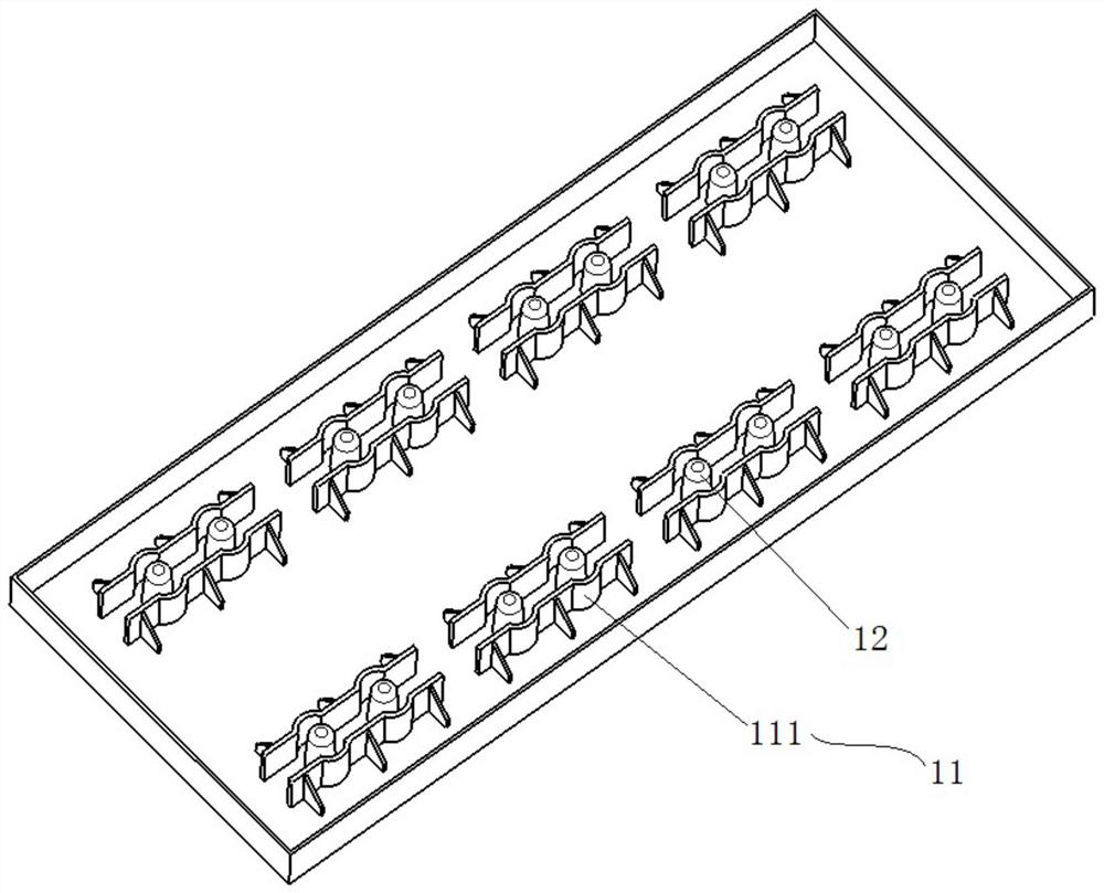
[0044] Such as figure 2As shown, the cover plate 1 includes a rectangular box-shaped body, and the inner surface of the box...
Embodiment 2
[0050] Such as Figure 5 As shown, on the basis of Embodiment 1, the side plate 3 includes two cross bars 31 and a connecting plate 32, and the two cross bars 31 are respectively connected to the top and bottom of the connecting plate 32, and the connecting plate 32 has a plurality of intervals The notch 33 provided, the notch 33 is rectangular, is arranged on the bottom of the connecting plate 32, as Figure 7 As shown, the side of the electric core 5 has a concave block 52, the concave block 52 protrudes from the gap 33, one end of the buckle 6 is rotatably connected to the side plate 3, and the other end of the buckle 6 snaps into the Concave block 52.
[0051] Such as Figure 5 As shown, the side plate 3 has a plurality of pin connecting grooves 34 arranged at intervals, the pin connecting grooves 34 are arc-shaped slideway structures, and the pin connecting grooves 34 are arranged on the horizontal bar 31 located below, There are shaft holes on both sides of the slidew...
Embodiment 3
[0054] Such as Figure 5 Said, on the basis of the first or second embodiment above, the two ends of the side plate 3 have first connecting holes 35, such as Figure 8 As shown, the two ends of the end plate 4 have second connection holes 41 , and the end plate 4 is connected to the side plate 3 through the first connection hole 35 and the second connection hole 41 by bolts.
[0055] Among them, such as Figure 5 As shown, the two cross bars 31 of the side plate 3 protrude from the connecting plate 32, and the two cross bars 31 and the connecting plate 32 form a horizontal concave structure, and the first connecting holes 35 are respectively arranged on the two cross bars. 31, respectively located at the top and bottom of the horizontal concave structure, the two first connecting holes 35 are located on the same axis, as Figure 8 As shown, the end of the end plate 4 has a convex structure that can be snapped into the groove of the concave structure, and the second connectin...
PUM
 Abstract
Description
Claims
Application Information
 - R&D
- Intellectual Property
- Life Sciences
- Materials
- Tech Scout
- Unparalleled Data Quality
- Higher Quality Content
- 60% Fewer Hallucinations
Browse by: Latest US Patents, China's latest patents, Technical Efficacy Thesaurus, Application Domain, Technology Topic, Popular Technical Reports.
© 2025 PatSnap. All rights reserved.Legal|Privacy policy|Modern Slavery Act Transparency Statement|Sitemap|About US| Contact US: help@patsnap.com