Film covering and flattening device suitable for aluminum plates with different thicknesses

An aluminum plate and lamination technology, applied in the field of aluminum plate lamination and flattening device, can solve the problems of difficult bubble treatment, poor functionality, and inability to combine together, so as to meet the needs of lamination, reduce manual processes, and reduce labor intensity. Effect

Pending Publication Date: 2021-04-06
吴甲平
8 Cites 1 Cited by

AI-Extracted Technical Summary

Problems solved by technology

Although this device can flatten the air bubbles generated after the aluminum plate is coated to a certain extent, it can only flatten the aluminum plate in one direction, and it is difficult to...

Method used

On the basis of embodiment 1, as shown in Figure 1 and Figure 4, the adjustment mechanism 5 that is used to adjust the height of swivel frame 4-9 is located at the bottom side of slip ring 4-5, adjustment mechanism 5 includes a card seat 5-1 and a bolt 5-2, the card seat 5-1 is fixed on the bottom side of the bottom of the sliding ring 4-5 and is located below the support frame 4-1, and a bolt is provided at the lower end of the card seat 5-1 Hole and bolt 5-2 rotation type is located in the bolt hole on the deck 5-1, and one end of bolt 5-2 can contact with the threaded hole on the rotating shaft one 4-7, and bolt 5-2 is used for rotating shaft - 4-7 plays the role of supporting limit, and bolt 5-2 cooperates with rotating shaft - 4-7 to adjust the position of swivel frame 4-9, which is beneficial to the lamination and flattening operation of aluminum plates with different thicknesses.
Working principle: the staff first pulls the clamping disc 2-6 to move forward so that the right end of the clamping disc 2-6 is separated from the unwinding rod 2-2, and the rolled film is placed on the unwind...

Abstract

The invention relates to an aluminum plate processing device, in particular to a film covering and flattening device suitable for aluminum plates with different thicknesses, and aims to solve the problems that bubbles generated after an aluminum plate is covered with a film cannot be completely eliminated by an existing aluminum plate flattening device, the phenomenon that the film is easy to fall off is easily caused, and the aluminum plate film covering and flattening processes cannot be combined together. The film covering and flattening device suitable for aluminum plates with different thicknesses comprises a base, an unreeling mechanism, a primary flattening mechanism and a rotary flattening mechanism and the like, wherein the unreeling mechanism is arranged on the upper side surface of one end of the base; the primary flattening mechanism is arranged on one side surface of the base; and the rotary flattening mechanism is arranged on the base. Two movable rollers can laminate the laminating film on the aluminum plate, and can transversely flatten the laminated film; a rotary frame drives four pressure rollers to rotate, so that the four pressure rollers can perform all-around flattening operation on the laminating film, and thus, the bubbles generated after film laminating are completely removed.

Technology Topic

Image

  • Film covering and flattening device suitable for aluminum plates with different thicknesses
  • Film covering and flattening device suitable for aluminum plates with different thicknesses
  • Film covering and flattening device suitable for aluminum plates with different thicknesses

Examples

  • Experimental program(3)

Example Embodiment

[0022] Example 1
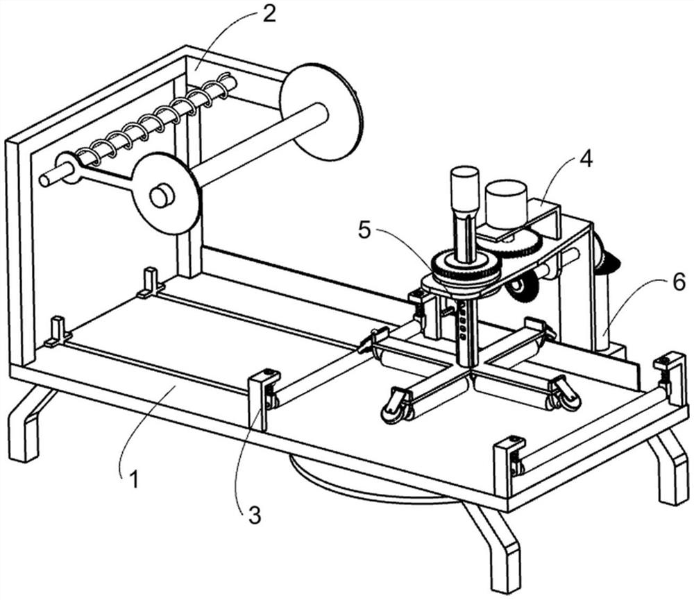
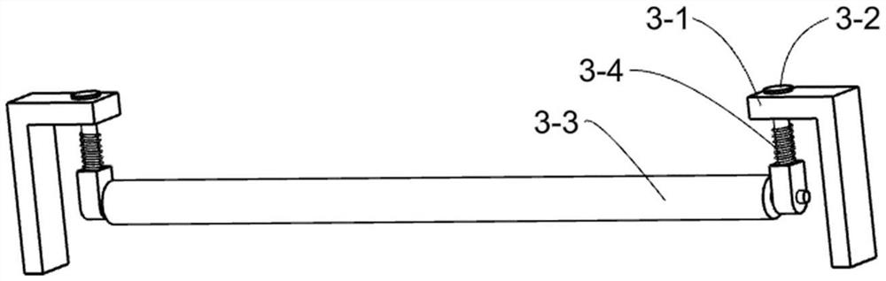
[0023] A flattening device suitable for aluminum plates with different thicknesses, such as Figure 1-6 As shown, it includes a base 1, an unwinding mechanism 2, a preliminary flattening mechanism 3, a rotary flattening mechanism 4 and an adjusting mechanism 5. The unwinding mechanism 2 for placing the film roll is located on the upper side of one end of the base 1, and is used for The preliminary flattening mechanism 3 for attaching the film to the aluminum plate is provided on the upper side of the base 1, the rotary flattening mechanism 4 for performing an omnidirectional flattening operation on the film is provided on the base 1, and the adjustment mechanism 5 is provided. on the rotary flattening mechanism 4.
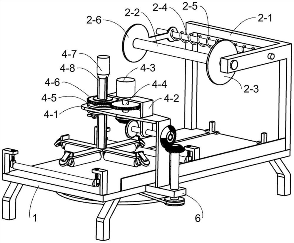
[0024] Further, the unwinding mechanism 2 includes an unwinding rack 2-1, an unwinding rod 2-2, a fixed disk 2-3, a fixed rod 2-4, a tension spring 2-5 and a clamping disk 2-6. 2-1 is fixed on one end of the base 1, the unwinding rod 2-2 used to place the film with different widths is fixed on one end of the upper part of the unwinding frame 2-1, and the fixing plate 2-3 is fixed on the unwinding rod 2 -2 and close to the unwinding rack 2-1, the fixing rod 2-4 is fixed on the unwinding rack 2-1 and close to the unwinding rod 2-2, and the clamping plate 2-6 is movably arranged on the fixing rod 2-4, and the clamping disc 2-6 is in sliding contact with the unwinding rod 2-2. The clamping disc 2-6 cooperates with the fixing disc 2-3 to limit the position of the rolled film. A tension spring 2-5 is arranged between the tightening plate 2-6 and the unwinding frame 2-1, and the fixing rod 2-4 passes through the tension spring 2-5.
[0025] Further, the preliminary flattening mechanism 3 includes a mounting frame 3-1, a telescopic rod 3-2, a movable roller 3-3 and a telescopic spring 3-4, and two sets of symmetrical mounting frames 3-1 are fixed on the upper side of the base 1. , the two sets of mounting brackets 3-1 are provided with telescopic rods 3-2 in a sliding type, and the lower ends of the two sets of telescopic rods 3-2 are provided with rotating types for attaching the film to the aluminum plate and pressing the film laterally. The movable roller 3-3 for horizontal operation, the movable roller 3-3 is located above the base 1, the lower end of the telescopic rod 3-2 and the bottom side of the mounting frame 3-1 are provided with a telescopic spring 3-4 and the telescopic rod 3- 2 Pass through the telescopic springs 3-4.
[0026] Further, the rotary flattening mechanism 4 includes a support frame 4-1, a support plate 4-2, a motor 4-3, a power shaft 4-4, a sliding ring 4-5, a power gear 4-6, a rotating shaft 4-7 , the guide bar 4-8, the rotating frame 4-9, the pressing roller 4-10, the side frame 4-11 and the movable wheel 4-12, the support frame 4-1 is fixed on one side of the base 1, and the pallet 4- 2 is fixed on the support frame 4-1, the motor 4-3 is fixed on the upper side of the upper part of the support plate 4-2, the power shaft 4-4 is set on the support frame 4-1 through the bearing, and the power shaft 4-4 is The upper end is fixedly connected with the output end of the motor 4-3, the sliding ring 4-5 is rotatably arranged at one end of the support frame 4-1, and a power gear 4-6 is fixedly arranged on the power shaft 4-4 and is located in the support frame 4 Between -1 and the support plate 4-2, another power gear 4-6 is fixed on the sliding ring 4-5, the two power gears 4-6 mesh with each other, and the rotating shaft 4-7 is slidably arranged on the sliding ring 4 -5 and ten threaded holes are opened on the rotating shaft one 4-7, three guide bars 4-8 are fixed on the peripheral side of the rotating shaft one 4-7, and the guide bars 4-8 and the inner part of the sliding ring 4-5 are fixed Ring sliding contact, the rotating frame 4-9 is fixedly arranged on the lower end of the rotating shaft 1 4-7 and the three guide bars 4-8, and the rotating frame 4-9 is rotatably provided with four for all-round pressure on the film. The flat-operated pressing rollers 4-10 and the four pressing rollers 4-10 work together to completely eliminate the air bubbles generated when the film is applied. The ends of the rotating frame 4-9 are fixed with side frames 4-11 and movable wheels 4. -12 is rotatably arranged on the side frame 4-11.
[0027] Working principle: The staff first pulls the clamping disc 2-6 to move forward to separate the right end of the clamping disc 2-6 from the unwinding rod 2-2, and places the rolled film on the unwinding rod 2-2. Next, the worker puts the right end of the clamping plate 2-6 back on the unwinding rod 2-2, and the clamping plate 2-6 and the fixing plate 2-3 cooperate with each other to limit the position of the rolled film. Since the position of the clamping plate 2-6 on the unwinding rod 2-2 can be adjusted, the rolls of different widths can be placed on the unwinding rod 2-2, which is convenient to meet the requirements of different widths of aluminum plates. The film needs; then the staff places the aluminum plate on the base 1, and pulls one end of the film to be in close contact with the right end of the aluminum plate. After all the preparations are done, the worker first starts the motor 4-3 to rotate counterclockwise, and then pushes the aluminum plate to move to the right, the aluminum plate will continuously pull out the film from the film roll. When in contact, the first movable roller 3-3 can cover the film on the aluminum plate, and can perform the initial horizontal flattening operation on the laminated film, so as to preliminarily deal with some air bubbles generated when the film is applied.
[0028] The staff continues to push the aluminum plate to the bottom of the pressing roller 4-10, the motor 4-3 will drive one of the power gears 4-6 to rotate counterclockwise through the power shaft 4-4, and one of the power gears 4-6 will pass through the other meshed with it. The power gear 4-6 will drive the sliding ring 4-5, the rotating shaft one 4-7 and the guide bar 4-8 to rotate clockwise, the rotating shaft one 4-7 and the guide bar 4-8 can drive the rotating frame 4-9 clockwise Rotating, the rotating frame 4-9 will drive the four pressing rollers 4-10 to rotate clockwise. At this time, the four pressing rollers 4-10 can flatten the film in all directions, so that the film and the aluminum plate can be more flattened. Lamination can further eliminate the bubbles generated after the film is applied, and at the same time, some bubbles located on the edge of the aluminum plate can also be eliminated. When the aluminum plate is pushed to be in contact with the second movable roller 3-3, the second movable roller 3-3 can horizontally flatten the film covered on the aluminum plate again, so that the film can adhere to the aluminum plate. It is tighter to prevent the film from falling off during later handling, and it can also completely eliminate the bubbles generated when the film is applied. When an aluminum plate is covered with film, the staff needs to cut off the film.

Example Embodiment

[0029] Example 2
[0030] On the basis of Example 1, as figure 1 and Figure 4 As shown, the adjusting mechanism 5 for adjusting the height of the rotating frame 4-9 is provided on the bottom side of the sliding ring 4-5, and the adjusting mechanism 5 includes a clamping seat 5-1 and a bolt 5-2. A bolt fixed on the bottom side of the bottom of the sliding ring 4-5 and located below the support frame 4-1, a bolt hole is provided at the lower end of the socket 5-1, and the bolt 5-2 is rotatably arranged on the socket 5-1 In the hole, one end of the bolt 5-2 can be in contact with the threaded hole on the rotating shaft 1 4-7. The bolt 5-2 is used to support and limit the rotating shaft 1 4-7. The bolt 5-2 is connected to the rotating shaft. A 4-7 coordination can adjust the position of the rotating frame 4-9, which is beneficial to the lamination and flattening operation of aluminum plates with different thicknesses.
[0031] Working principle: In order to cover different thicknesses of aluminum plates, the staff can adjust the height of the rotating frame 4-9 according to the thickness of the aluminum plate before filming the aluminum plate, so that the four pressing rollers 4-10 Can be in contact with the upper surface of aluminum plates of different thicknesses. The staff rotates the bolt 5-2 to separate it from the threaded hole on the rotating shaft one 4-7, and then pulls the rotating shaft one 4-7 to move up, which will push the rotating shaft one 4-7 to move down. When the rotating shaft 1 4-7 moves upward, it will drive the guide bar 4-8, the rotating frame 4-9 and the pressing roller 4-10 to move upward. At this time, the distance between the pressing roller 4-10 and the base 1 will increase. , suitable for lamination processing of thicker aluminum plates; when the rotating shaft 1 4-7 moves down, it will drive the guide bar 4-8, the rotating frame 4-9 and the pressure roller 4-10 to move down. At this time, the pressure roller The distance between 4-10 and the base 1 will be reduced, which is suitable for lamination processing of thinner aluminum plates. After the height of the rotating frame 4-9 is adjusted, the staff needs to turn the bolts 5-2 into the corresponding threaded holes, so that the bolts 5-2 can limit the position of the rotating shaft 1 4-7. Since the telescopic rod 3-2 can drive the movable roller 3-3 to move up and down, the height of the movable roller 3-3 can be automatically adjusted when the aluminum plates with different thicknesses are pushed to contact the movable roller 3-3, so as to meet the requirements of different aluminum plates. Lamination needs.

Example Embodiment

[0032] Example 3
[0033] On the basis of Example 2, as Figure 1-2 , Figure 4 and Image 6 As shown, it also includes a pushing mechanism 6 for pushing the aluminum plate on the base 1. The pushing mechanism 6 is arranged on the base 1 and is connected with the rotary flattening mechanism 4. The pushing mechanism 6 includes a transmission shaft 6-1, a bevel gear One 6-2, missing angle bevel gear 6-3, rotating shaft two 6-4, bevel gear two 6-5, pulley one 6-6, rotating shaft three 6-7, pulley two 6-8, belt 6 -9, the turntable 6-10, the push frame 6-11 and the connecting rod 6-12, the transmission shaft 6-1 is set at the lower end of the support plate 4-2 through the bearing and passes through the support frame 4-1, one of the bevel gears is a 6-2 is fixed on the lower end of the power shaft 4-4, another bevel gear 6-2 is fixed on the end of the transmission shaft 6-1 close to the support plate 4-2, the two bevel gears 6-2 mesh with each other, The cutaway bevel gear 6-3 is fixed on the other end of the transmission shaft 6-1 and is close to the upper part of the support frame 4-1, and the second rotating shaft 6-4 is set on the base 1 through a bearing and is close to the support frame 4-1 The second bevel gear 6-5 is fixed on the upper end of the second rotating shaft 6-4 and meshes with the missing angle bevel gear 6-3, and the first pulley 6-6 is fixed at the end of the second rotating shaft 6-4 that is close to the base 1 , the rotating shaft three 6-7 is set at the bottom of the base 1 through the bearing, the second pulley 6-8 is fixedly arranged on the rotating shaft three 6-7, the pulley one 6-6 and the second pulley 6-8 are connected with a The belt 6-9, the turntable 6-10 are fixed on the lower end of the rotating shaft 3 6-7, the base 1 is provided with two chutes, and the push frame 6-11 is slidably arranged in the two chutes, and the push frame 6-11 can Push the aluminum plate on the base 1 to move to the right to carry out the lamination and flattening operation, which is beneficial to reduce the labor intensity of the staff. A connecting rod 6-12 is rotatably connected between the bottom of the push frame 6-11 and the turntable 6-10, and the turntable 6 -10 Through the connecting rod 6-12, the push frame 6-11 can be driven to reciprocate left and right.
[0034] Working principle: The power shaft 4-4 will drive the transmission shaft 6-1 and the missing bevel gear 6-3 to rotate clockwise through the two bevel gears 1 6-2. When engaged, it will drive the second rotating shaft 6-4 to rotate counterclockwise, and the rotating shaft 2 6-4 will drive the second pulley 6-8, the third rotating shaft 6-7 and the turntable 6 through the first pulley 6-6 and the belt 6-9. -10 rotates counterclockwise, the turntable 6-10 will drive the push frame 6-11 to reciprocate left and right through the connecting rod 6-12. When the push frame 6-11 moves to the right, it can push the aluminum plate on the base 1 to move to the right to perform the lamination and flattening operation, thereby reducing the manual process of the staff in the process of laminating the aluminum plate; when the push frame 6-11 moves to the left After moving and resetting, the missing angle bevel gear 6-3 just disengages from the second bevel gear 6-5, and the turntable 6-10 will temporarily stop rotating. At this time, the staff can place the next aluminum plate that needs to be covered on the base 1. . After all the aluminum plates are covered and flattened, the staff turns off the motors 4-3.

PUM

no PUM

Description & Claims & Application Information

We can also present the details of the Description, Claims and Application information to help users get a comprehensive understanding of the technical details of the patent, such as background art, summary of invention, brief description of drawings, description of embodiments, and other original content. On the other hand, users can also determine the specific scope of protection of the technology through the list of claims; as well as understand the changes in the life cycle of the technology with the presentation of the patent timeline. Login to view more.

Similar technology patents

Characteristic real-time releasing system and method

ActiveCN102739633AReduce manual processesLabor savingTransmissionClient-sideTransmission medium
Owner:ZHUHAI BAOQU TECH CO LTD

Car sunshade screen front line sewing tooling

PendingCN109385756AReduce manual processesReduce scrap rateWork-feeding meansTextileCivil engineering
Owner:上工富怡智能制造(天津)有限公司

Logistics order number prefetching method, electronic equipment and storage medium

PendingCN112907185AShipping Process SimplifiedReduce manual processesBuying/selling/leasing transactionsLogisticsOrder systemService provider
Owner:深圳市腾辉信息技术有限公司

Classification and recommendation of technical efficacy words

  • Reduce manual processes

Ultrathin double-sided nano-silver capacitive screen and preparation method thereof

PendingCN111208921AEtching is achieved quicklyReduce manual processesInput/output processes for data processingPhysicsChemistry
Owner:SHENZHEN HUAKE COMM TECH CO LTD

Car sunshade screen front arc sewing tooling

PendingCN109385757AReduce manual processesReduce scrap rateWork-feeding meansFlangingEngineering
Owner:上工富怡智能制造(天津)有限公司

Characteristic real-time releasing system and method

ActiveCN102739633AReduce manual processesLabor savingTransmissionClient-sideTransmission medium
Owner:ZHUHAI BAOQU TECH CO LTD

People also interested in

Why Eureka
Try Eureka