
3D printing head capable of remotely supplying air

A printing head, 3D technology, applied in the field of 3D printing head, can solve the problems of not supporting higher melting point, high surface temperature of heating block, large loss of printing area, etc., to prevent heat loss, high heating accuracy, and large printing area. Effect

Inactive Publication Date: 2021-04-06
毕波
View PDF7 Cites 0 Cited by
  • Summary
  • Abstract
  • Description
  • Claims
  • Application Information

AI Technical Summary

Problems solved by technology

[0006] 1. The printing accuracy is poor, because the print head body is heavy and the vibration generated by the fan operation will affect the printing accuracy;
[0007] 2. The heating and cooling are slow, because the heat needs to be conducted through the heating block;
[0008] 3. The heating accuracy is poor, because the distance between the heating tube and the temperature measuring head is far away, and the temperature is biased;
[0009] 4. The loss of printing area is large. The reason is that the traditional printing head is large in size, which makes the moving space limited and part of the printing area is lost;
[0010] 5. There are potential safety hazards because the surface temperature of the heating block is high and it is easy to burn;
[0011] 6. Energy waste, because a lot of heat will be wasted through the cooling plate and cannot be reused;
[0012] 7. Materials with a higher melting point are not supported, because too high a temperature can easily cause the Teflon tube to melt and the structure to be destroyed;
[0013] 8. The printing temperature will continue to rise in a confined space, because the local heat cycle formed by the fan will cause the heat accumulation temperature to rise

Method used


Image

  • 3D printing head capable of remotely supplying air
  • 3D printing head capable of remotely supplying air
  • 3D printing head capable of remotely supplying air

Examples


Embodiment Construction

[0039] The following will clearly and completely describe the technical solutions in the embodiments of the present invention with reference to the accompanying drawings in the embodiments of the present invention. Obviously, the described embodiments are only some, not all, embodiments of the present invention. Based on the embodiments of the present invention, all other embodiments obtained by persons of ordinary skill in the art without making creative efforts belong to the protection scope of the present invention.

[0040] In the description of the present invention, it should be noted that the orientation or positional relationship indicated by the terms "vertical", "upper", "lower", "horizontal" etc. is based on the orientation or positional relationship shown in the drawings, and is only In order to facilitate the description of the present invention and simplify the description, it does not indicate or imply that the device or element referred to must have a specific o...


PUM


Abstract

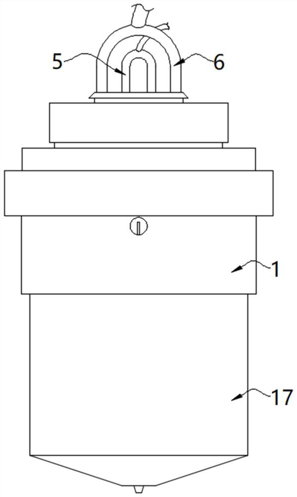
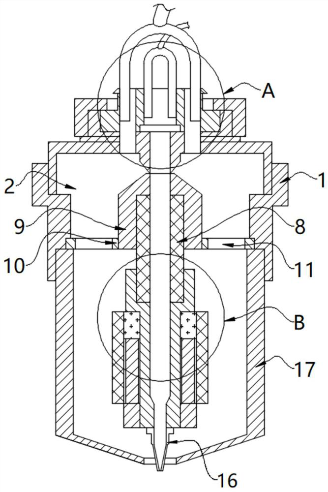
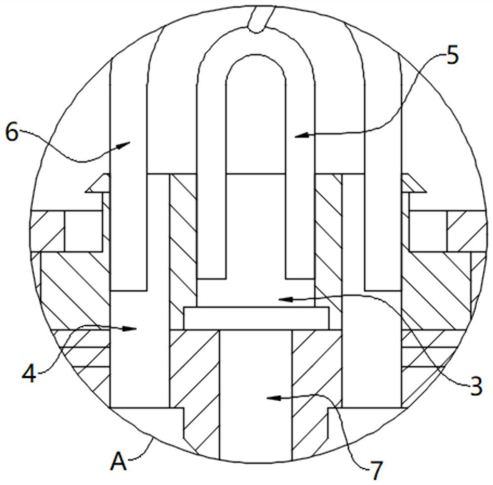
The invention relates to the technical field of 3D printing heads, and discloses a 3D printing head capable of remotely supplying air. The 3D printing head comprises a shell, an air cavity is formed in the shell, an air cover is fixedly installed at the bottom of the shell, a feeding channel is coaxially arranged in the air cavity, and a heat insulation pipe is arranged on the outer wall of the feeding channel; a fixing sleeve is fixedly installed on the outer wall of the upper portion of the heat insulation pipe, a heat conduction pipe is fixedly installed on the outer wall of the lower portion of the heat insulation pipe, heat generated by a heater is transmitted to a heat dissipation plate through the heat conduction pipe, the heat insulation pipe and the fixing sleeve, and air entering from an air supply pipe can effectively dissipate heat of the heat dissipation plate; and after the heat is dissipated, the air with heat is blown to a printing material through circular through holes under the guidance of the air cover, the printing material is helped to be rapidly cooled and cured, the printing effect is better, more energy is saved, more environment is protected, the design is novel, and the 3D printing head has the advantages of being high in printing precision, rapid in heating and cooling, high in heating precision, large in printing area, safe, stable and capable of repeatedly utilizing resources.

Description

technical field [0001] The invention relates to the technical field of 3D printing heads, in particular to a 3D printing head for remote air supply. Background technique [0002] FDM 3D printing technology is a widely used 3D printing technology. Compared with other methods such as light curing and laser sintering, 3D printers using FDM have certain advantages in terms of manufacturing cost and use cost. [0003] At present, in FDM 3D printing technology, the print head is still its core component. The function of the print head is to heat and melt the filamentous hot-melt material, and then accumulate the melted material in the designated area one after another with the force applied to the material and the movement of the print head itself. [0004] The mainstream FDM 3D printing head on the market is mainly composed of nozzles, heating rods, temperature sensing heads, heating blocks, throats, Teflon tubes, cooling plates and fans. The principle is mainly that the filam...

Claims


Application Information

Patent Timeline
Patent Type & Authority Applications(China)
IPC IPC(8): B29C64/209B29C64/295B29C64/364B29C64/379B33Y30/00B33Y50/02
CPCB29C64/209B29C64/364B29C64/379B29C64/295B33Y50/02B33Y30/00
Inventor 毕波
Owner 毕波
Learn More