
Unmanned aerial vehicle

A technology for drones and cabins, applied in the field of drones, can solve problems such as affecting the normal operation of drones, inability to dissipate heat from electronic components, and damage to electronic components.

Inactive Publication Date: 2021-04-06
BEIJING AIRLANGO TECH CO LTD
View PDF0 Cites 2 Cited by
  • Summary
  • Abstract
  • Description
  • Claims
  • Application Information

AI Technical Summary

Problems solved by technology

[0002] When the drone is working, the electronic components in the cabin (such as computer printed circuit boards and computer chips set on the computer printed circuit boards, power control boards and power chips set on the power control boards, etc.) will generate heat. If the electronic components cannot be effectively dissipated, the electronic components will be damaged due to overheating, which will affect the normal operation of the drone.
In the prior art, the purpose of dissipating heat for electronic components is usually achieved by dissipating heat from the space inside the cabin. The method of heat dissipation cannot ensure that the airflow entering the cabin flows through the electronic components and takes away the heat of the electronic components. control its temperature within a certain range

Method used


Image

  • Unmanned aerial vehicle
  • Unmanned aerial vehicle
  • Unmanned aerial vehicle

Examples


Embodiment Construction

[0040] Specific embodiments of the present disclosure will be described in detail below in conjunction with the accompanying drawings. It should be understood that the specific embodiments described here are only used to illustrate and explain the present disclosure, and are not intended to limit the present disclosure.

[0041] In this disclosure, unless stated to the contrary, the used orientation words such as "up and down" are usually defined in the normal flight state of the UAV, specifically, when the UAV is in normal flight, pointing to The direction toward the sky is up, and the direction toward the ground is down. "Inner and outer" refer to the inside and outside of the corresponding structure or part outline.

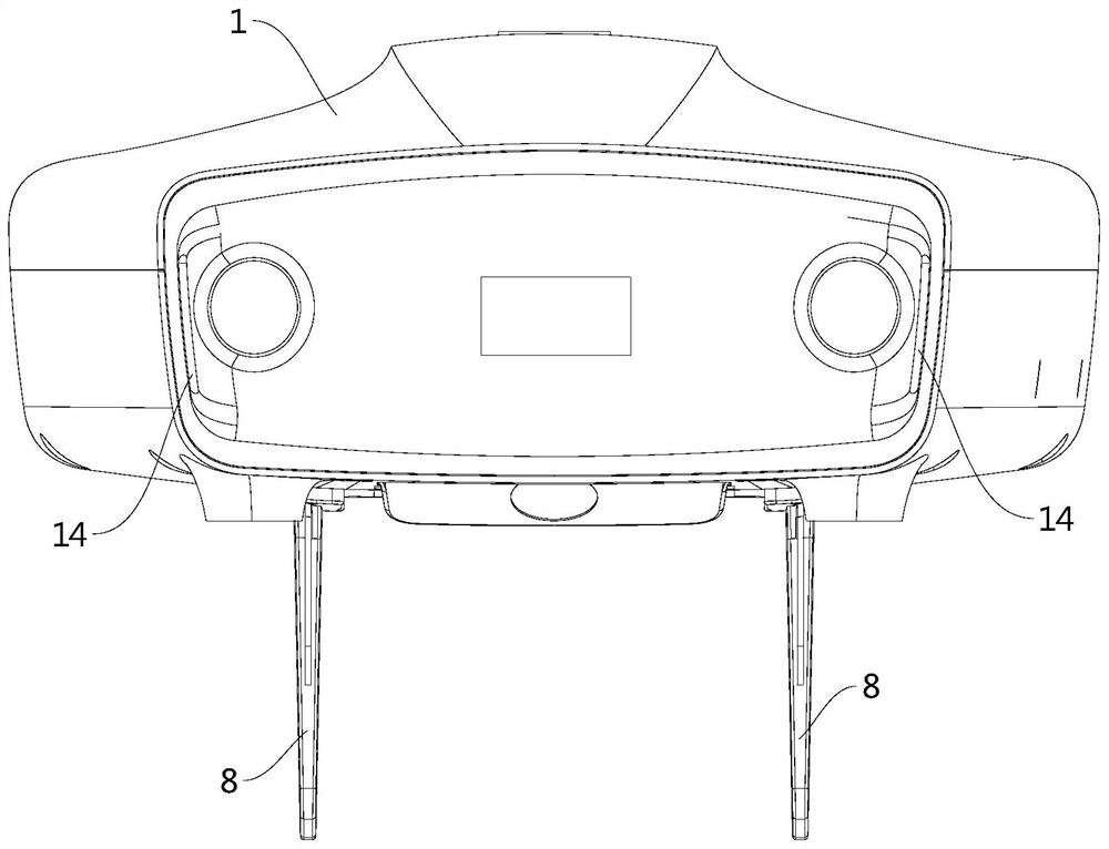
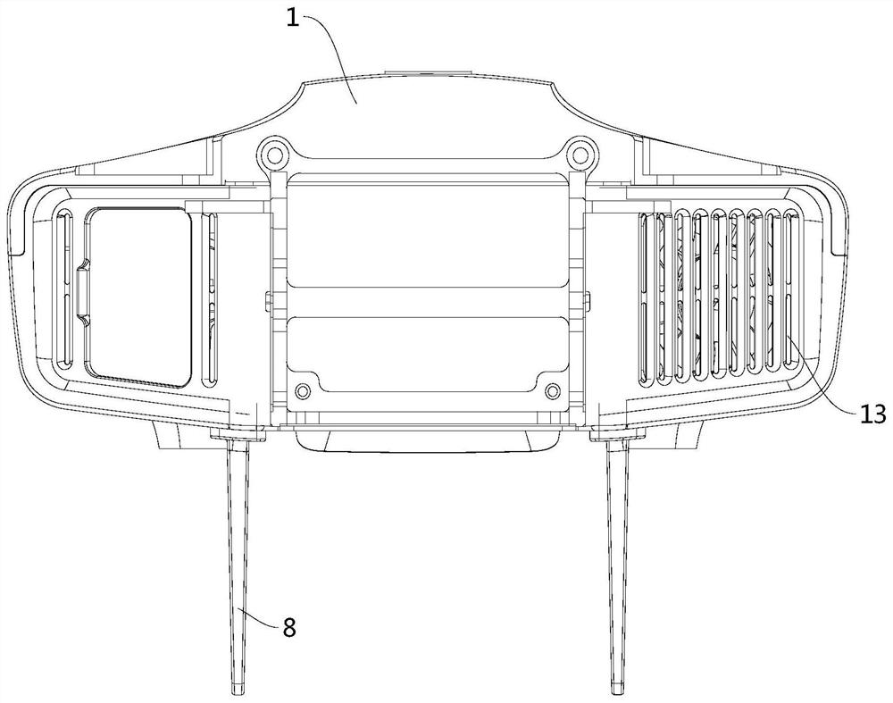
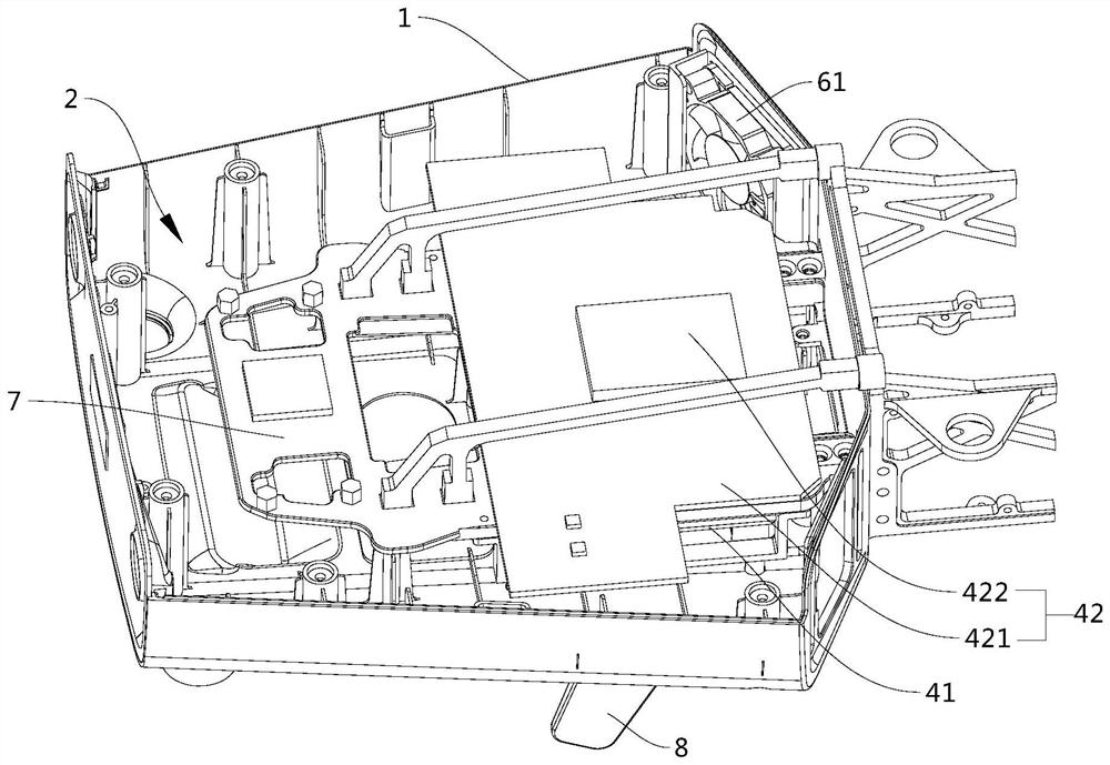
[0042] Such as Figure 1 to Figure 10 As shown, the present disclosure provides a drone, including a casing 1 , a first electronic component 41 , a first heat dissipation assembly 5 and a second heat dissipation assembly. Wherein, the casing 1 defines the e...


PUM


Abstract

The disclosure relates to an unmanned aerial vehicle that is characterized in that the unmanned aerial vehicle comprises a machine shell, a cabin is defined by the machine shell, the cabin is provided with a closed sub-chamber, a first ventilation opening and a second ventilation opening which communicate with the sub-chamber are formed in the machine shell, and a first cabin air opening and a second cabin air opening which communicate with the space outside the sub-chamber in the cabin are formed in the machine shell; besides, the unmanned aerial vehicle includes a first electronic component disposed in the cabin, a first heat dissipation assembly, and a second heat dissipation assembly; the first heat dissipation assembly comprises a heat dissipation structure and a first heat dissipation fan which are arranged in the sub-chamber, the heat dissipation structure is used for exchanging heat with the first electronic component, the first heat dissipation fan is used for enabling an airflow flowing through the heat dissipation structure to be generated in the sub-chamber, and the airflow enters from one of the first ventilation opening and the second ventilation opening and flows out from the other one; and the second heat dissipation assembly comprises a second heat dissipation fan arranged at the air opening of the first cabin, and the second heat dissipation fan is used for enabling the space outside the sub-chamber in the cabin to generate airflow.

Description

technical field [0001] The present disclosure relates to the technical field of drones, and in particular, to a drone. Background technique [0002] When the drone is working, the electronic components in the cabin (such as computer printed circuit boards and computer chips set on the computer printed circuit boards, power control boards and power chips set on the power control boards, etc.) will generate heat. If the electronic components cannot be effectively dissipated, the electronic components will be damaged due to overheating, which will affect the normal operation of the drone. In the prior art, the purpose of dissipating heat for electronic components is usually achieved by dissipating heat from the space inside the cabin. The method of heat dissipation cannot ensure that the airflow entering the cabin flows through the electronic components and takes away the heat of the electronic components. Control its temperature within a certain range. Contents of the inve...

Claims


Application Information

Patent Timeline
Patent Type & Authority Applications(China)
IPC IPC(8): B64C39/02B64C1/06H05K7/20B64C25/32
CPCB64C39/02B64C1/068H05K7/20863H05K7/20854B64C25/32B64U10/00
Inventor 王刚高焓郜奥林陆宏伟姜欣宏刘宝俊吴振凯毛一年初征
Owner BEIJING AIRLANGO TECH CO LTD
Learn More