
Ship lock head side pier combined template and installation method

A technology of combining formwork and formwork, which is applied to ship locks, ship lifting devices, formwork/formwork components, etc., can solve the problem of increasing the dead weight of the formwork and the amount of steel used for the pier at the head of the lock, increasing the construction cost, and the difficulty of erecting the formwork by the construction personnel. and other problems, to achieve the effect of safe and efficient installation method, reduce self-weight, improve installation efficiency and installation quality

Pending Publication Date: 2021-04-06
CHINA COMM 2ND NAVIGATIONAL BUREAU 3RD ENG
View PDF0 Cites 0 Cited by
  • Summary
  • Abstract
  • Description
  • Claims
  • Application Information

AI Technical Summary

Problems solved by technology

[0003] The formwork is usually welded by section steel and steel plate. In order to have sufficient strength and rigidity, the existing formwork for side pier trusses at gate head uses larger section steel and steel plate to increase its flexural section modulus and reduce its Stress value, but increased the self-weight and steel consumption of the head side pier formwork, increased the construction cost
[0004] There is no operating platform at the lower part of the formwork of the existing gate side pier. When the concrete of the gate side pier is poured in multiple layers, since there is no support point at the bottom of the formwork and no operating platform, it is very difficult for construction workers to support the formwork, and there are greater security risk

Method used


Image

  • Ship lock head side pier combined template and installation method
  • Ship lock head side pier combined template and installation method
  • Ship lock head side pier combined template and installation method

Examples


Embodiment Construction

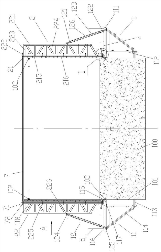
[0025] The present invention will be further described below in conjunction with accompanying drawing and the combined formwork embodiment of the ship lock head side pier of Hangzhou Babao Ship Lock.

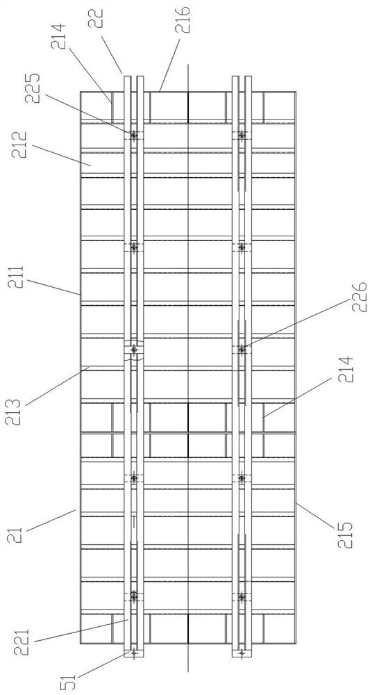
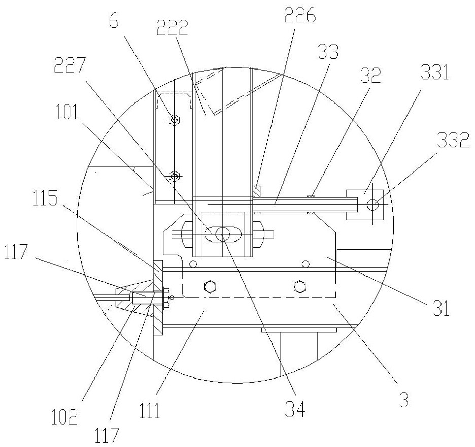
[0026] Such as figure 1 with figure 2 As shown, the present embodiment includes a cantilever hanger 1 and a truss formwork 2. The cantilever hanger 1 includes two parallel support tripods 11 and a pair of adjustable struts 12. The support tripod 11 includes a horizontal bar 111 and a vertical bar 112. , the lower cross bar 113 and the diagonal brace 114, one end of the horizontal bar 111 is vertically welded to the upper end of the vertical bar 112, and one end of the horizontal bar 111 is fixed on the pre-buried climbing anchor cone 102 in the upper part of the vertical side 101 of the poured concrete, vertical The lower end of the bar 112 is vertically welded to one end of the lower cross bar 113, and the other end of the lower cross bar 113 leans against the vertical side 1...


PUM


Abstract

The invention discloses a ship lock head side pier combined template. The ship lock head side pier combined template comprises a cantilever hanging frame and truss templates, wherein the cantilever hanging frame comprises a supporting triangular frame and a pair of adjustable supporting rods; and one end of a horizontal rod of the supporting triangular frame is fixed on a pre-buried climbing anchor cone which is poured with concrete. The upper and lower ends of the adjustable supporting rods are hinged with the middle part of a truss and the other end of the horizontal rod respectively; and the lower ends of the truss templates are vertically arranged at one end of the supporting triangular frame through a truss template position adjusting and fixing mechanism. An installation method disclosed by the invention comprises the following steps of: 1) mounting the supporting triangular frame; 2) mounting the truss templates at one end of the supporting triangular frame; 3) mounting the adjustable supporting rods; 4) fixing the truss templates; 5) mounting the second truss template and locking upper openings of one group of two truss templates; and 6) connecting the plurality of groups of truss templates to form a sealed framework template structure. According to the ship lock head side pier combined template, the self weight of the combined template is alleviated, the manufacturing cost is reduced, the bending strength and rigidity of the truss templates are improved and the safety of the ship lock head side pier combined template is improved.

Description

technical field [0001] The invention relates to a wall formwork of cast-in-place reinforced concrete, in particular to a combined formwork and an installation method for building the head and side pier of a ship lock, belonging to the technical field of hydraulic engineering construction. Background technique [0002] The ship lock is a key hydraulic structure for lifting ships or fleets in order to overcome the water level difference in the waterway transportation channel. Only by opening and closing the lock gate to adjust the water level can the channel maintain normal navigation. The cross-section of the front side pier of the ship lock formed by pouring reinforced concrete is in the shape of a trough, including the bottom plate and the side pier structures at both ends of the bottom plate. The formwork must be installed before the reinforced concrete is poured. The formwork structure and installation quality have a great influence on the construction quality and constru...

Claims


Application Information

Patent Timeline
Patent Type & Authority Applications(China)
IPC IPC(8): E04G13/00E04G17/16E04G17/14E04G9/06E02C1/00
CPCE04G13/00E04G17/16E04G17/14E04G9/06E02C1/00E04G2009/028Y02A10/30
Inventor 严小卫姚平茅兵海韩雨凡高建南宋业青王亮杨宇臣汪小川林宝玉徐文吉李宝成姚娟周启南
Owner CHINA COMM 2ND NAVIGATIONAL BUREAU 3RD ENG
Learn More