Pneumatic main cut-off change-over valve

A technology for switching valves and cylinders, applied in high-pressure air circuit breakers, valve details, multi-way valves, etc., can solve the problems of complex overall structure and poor reliability, and achieve the effect of simplicity, compactness, high reliability and compact structure

Inactive Publication Date: 2021-04-06
BEIJING CED RAILWAY ELECTRIC TECH
View PDF9 Cites 0 Cited by
  • Summary
  • Abstract
  • Description
  • Claims
  • Application Information

AI Technical Summary

Problems solved by technology

[0003] The vacuum circuit breaker switching valve in the prior art has a complex overall structure and poor reliability

Method used


Image

  • Pneumatic main cut-off change-over valve
  • Pneumatic main cut-off change-over valve
  • Pneumatic main cut-off change-over valve

Examples


specific Embodiment approach

[0023] The preferred embodiment of the pneumatic main break switching valve of the present invention is:

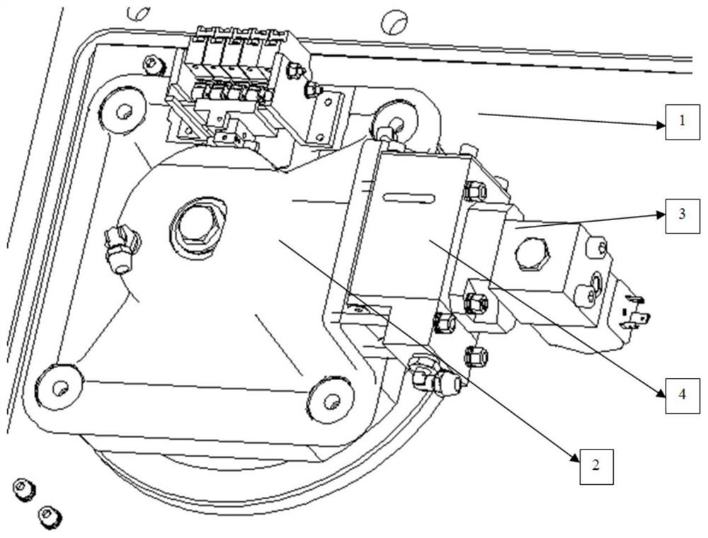
[0024] The vacuum circuit breaker includes a base 1, a cylinder 2, and a solenoid valve 3. The cylinder 2 is installed on the base 1, and a switch valve 4 is installed on the cylinder 2. The solenoid valve 3 Installed on the switching valve 4;

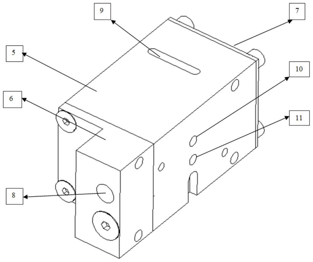
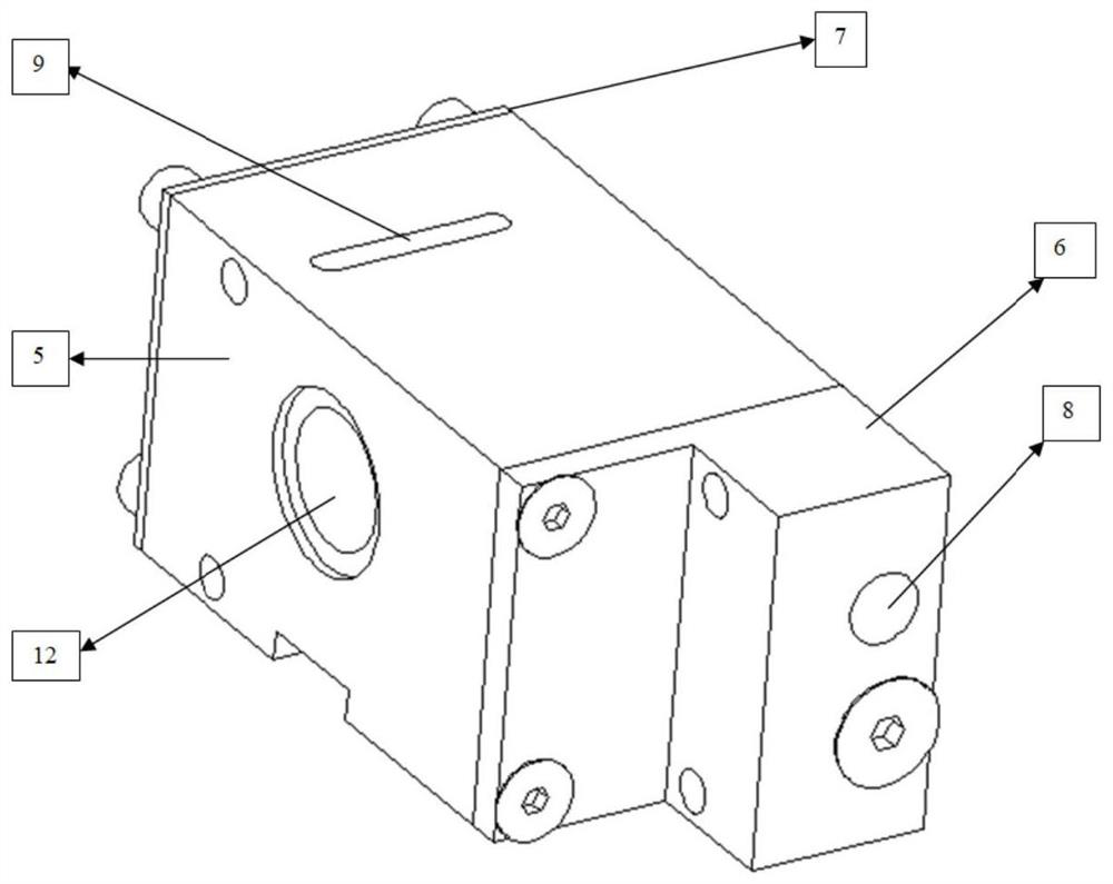
[0025] The external structure of the switching valve 4 includes a switching valve body 5, a top plate 6 and a bottom plate 7, the top plate 6 is provided with a total air intake hole 8, and the side of the switching valve body 5 is provided with an exhaust hole 9, The side of the switching valve body 5 close to the solenoid valve 3 is provided with a solenoid valve air inlet 10 and a solenoid valve gas outlet 11, and the side of the switching valve body 5 close to the cylinder 2 is provided with a cylinder inlet. Air port 12;

[0026] The internal structure of the switching valve 4 includes a poppet valve 13, a valve stem 14, a ...

specific Embodiment

[0038] The assembly structure of the conversion valve 4 in the vacuum circuit breaker is as follows: figure 1 As shown, it includes: base 1, cylinder 2, solenoid valve 3, switch valve 4, cylinder 2 is installed on base 1, switch valve 4 is installed on cylinder 2, solenoid valve 3 is installed on switch valve 4.

[0039] The external design structure of the conversion valve 4 is as follows: figure 2 and image 3 Shown: including switch valve body 5, top plate 6, bottom plate 7, total air intake hole 8, exhaust hole 9, solenoid valve air inlet 10, solenoid valve air outlet 11, cylinder air inlet 12, the changeover valve 4 consists of The switch valve body 5, the top plate 6 and the bottom plate 7 are composed, the total air intake hole 8 is the air intake hole on the top plate 6, the exhaust hole 9 is the exhaust hole on the switch valve body 5, the solenoid valve air inlet 10 and The solenoid valve air outlet 11 is the air inlet and the air outlet connected with the electro...


PUM


Abstract

The invention discloses a pneumatic main cut-off change-over valve. The valve comprises a base, an air cylinder, an electromagnetic valve and a change-over valve body, the change-over valve body comprises a change-over valve main body, a top plate and a bottom plate, a main air inlet hole is formed in the top plate, an exhaust hole is formed in the side face of the change-over valve main body, and an electromagnetic valve air inlet, an electromagnetic valve air outlet and an air cylinder air inlet are formed in the change-over valve main body. A lifting valve, a valve rod, a spring, a sealing body and a change-over valve piston are arranged in the change-over valve body. The change-over valve body is assembled in a vacuum circuit breaker base and between the electromagnetic valve and a main air cylinder, the change-over valve body effectively connects a gas circuit between a circuit breaker electromagnetic valve and the main air cylinder, the valve between the electromagnetic valve and the change-over valve body is controlled through external power supply and power failure, and switching of the gas circuit in the change-over valve body is achieved. Therefore, air intake and air exhaust of high-pressure air in the main air cylinder are achieved, and closing and breaking operations of the circuit breaker are achieved. The change-over valve is simple and compact in overall structure, high in reliability and capable of being widely applied.

Description

technical field [0001] The invention relates to a rail vehicle vacuum circuit breaker, in particular to a pneumatic main break switching valve, which is used for the pneumatic vacuum circuit breaker switching valve of a 25kV electrified railway. Background technique [0002] The vacuum circuit breaker is suitable for all types of electric locomotives and motor vehicles with 25kV main line AC. It is installed on the roof of the locomotive and the motor car or inside the high-voltage box. It is very important and directly affects the operation and operation of the train. When the train starts to run, it is necessary to close the circuit breaker to connect to the catenary. When the train needs to split the phase or remove the fault, the vacuum circuit breaker needs to cut off the circuit between the vehicle and the catenary, so as to protect the electrical equipment of the vehicle. The disconnection must switch the input and discharge of high-pressure air through the switching...

Claims


Application Information

Patent Timeline
Patent Type & Authority Applications(China)
IPC IPC(8): F16K11/044F16K31/122F15B13/044H01H33/02H01H33/38
CPCF16K11/044F16K31/122F15B13/044H01H33/02H01H33/38
Inventor 侯健伟张东远王俊峰雷志宇徐玉峰
Owner BEIJING CED RAILWAY ELECTRIC TECH
Why Eureka
Try Eureka