Multifunctional particulate matter drying mechanism

A granular and multi-functional technology, applied in the direction of non-progressive dryers, dryers, drying solid materials, etc., can solve the problems of moisture easily staying in the device, affecting normal operation, single function, etc.

Inactive Publication Date: 2021-04-06
周素河
View PDF0 Cites 3 Cited by
  • Summary
  • Abstract
  • Description
  • Claims
  • Application Information

AI Technical Summary

Problems solved by technology

[0004] Aiming at the deficiencies of the prior art, the present invention provides a multi-functional particle drying mechanism, which has various functions and can cool and sieve the dried particles, avoiding the influence of moisture staying in the device on the normal use of the device, etc., to solve the problem of It solves the problem that the single function cannot cool and sieve the dried particles, and the moisture is easy to stay in the device, which will affect the normal operation of the device.

Method used


Image

  • Multifunctional particulate matter drying mechanism
  • Multifunctional particulate matter drying mechanism
  • Multifunctional particulate matter drying mechanism

Examples


Embodiment 1

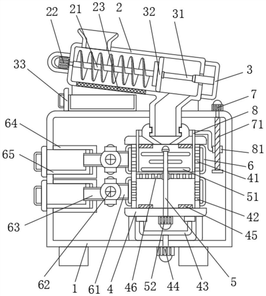
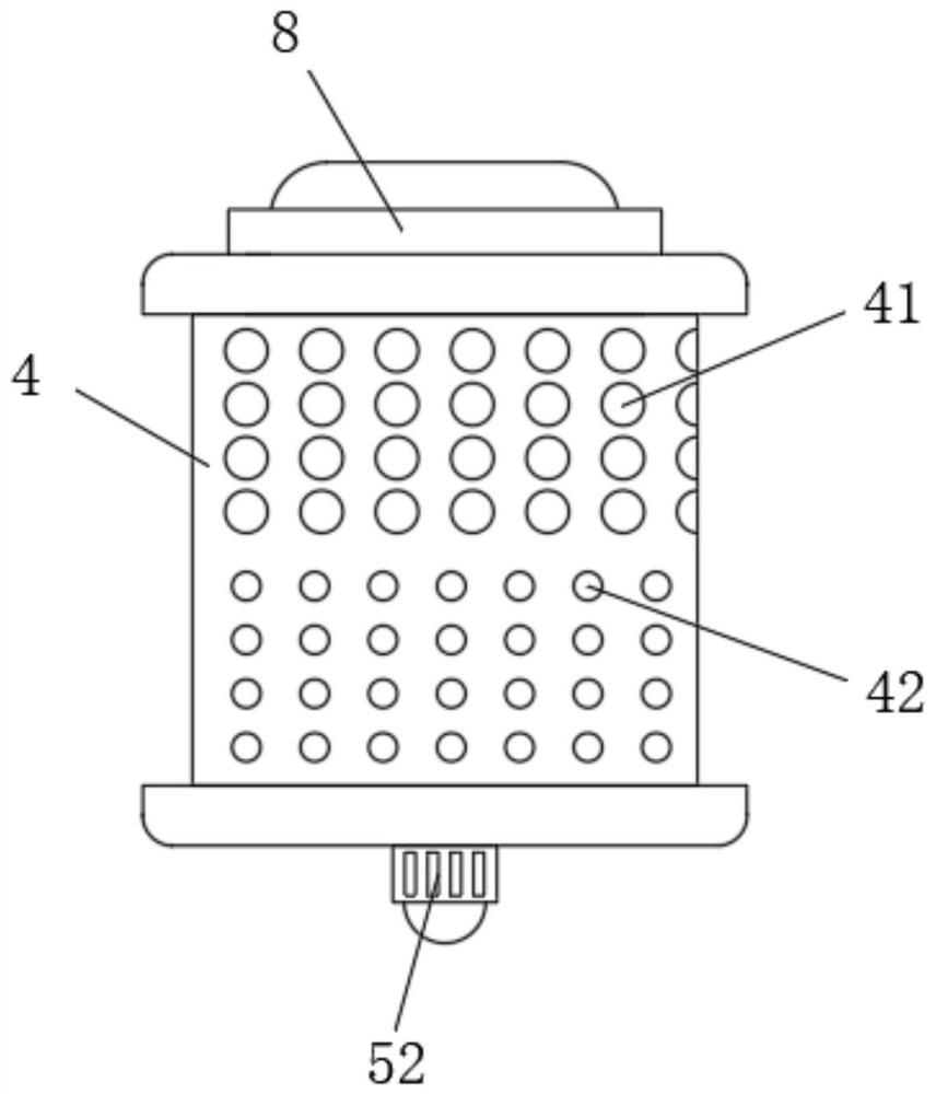
[0030] Example 1: See Figure 1-7 , the multifunctional particle drying mechanism of the present invention comprises an outer box 1, the top of the outer box 1 is fixedly connected with a feed pipe 2, the inside of the feed pipe 2 is rotatably connected with a screw feed rod 21, and the left side of the feed pipe 2 is fixedly connected There is a first motor 22, the bottom of the feeding pipe 2 is fixedly connected with a filter screen 23, the right side of the feeding pipe 2 is fixedly connected with a connecting plate 3, and the left side of the connecting plate 3 is fixedly connected with an electric telescopic rod 31, and the electric telescopic rod The left side of 31 is fixedly connected with a baffle 32, and the inside of the outer box 1 is rotatably connected with a drying barrel 4 at a position close to the right side, and a first filter hole 41 is ring-shaped on the surface of the drying barrel 4 near the top. 4 surface and the position near the bottom are provided w...

Embodiment 2

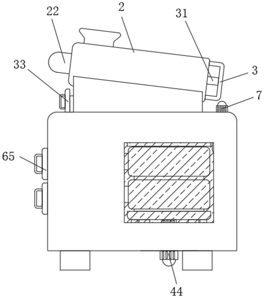
[0039] Example 2: See Figure 8 , a vacuum cleaner 9 is fixedly connected to the top of the outer box 1 and close to the left side, and the dust inlet pipe provided on the vacuum cleaner 9 is fixedly connected to the bottom of the feeding pipe 2 and corresponds to the position of the filter screen 23. The particulate matter in the pipe 2 has less water inclusions, but when dust and impurities are more mixed, the dust mixed in the particulate matter poured into the material pipe 2 can be sucked through the filter screen 23 by using the vacuum cleaner 9 and the filter screen 23, so as to avoid the inside of the particulate matter. The inclusion of dust affects subsequent processing operations.

[0040] When using the present invention, first start the electric telescopic rod 31, use the electric telescopic rod 31 to drive the baffle plate 32 to move to the left in the feeding pipe 2, then pour the particles that need to be dried into the feeding pipe 2, and start simultaneously ...


PUM


Abstract

The invention relates to the technical field of particle drying, and particularly discloses a multifunctional particle drying mechanism. The multifunctional particle drying mechanism comprises an outer box, a feeding pipe is fixedly connected to the top of the outer box, a spiral feeding rod is rotatably connected into the feeding pipe, a drying barrel is rotatably connected to the position, close to the right side, inside the outer box, first filtering holes are annularly formed in the surface, close to the top, of the drying barrel, second filtering holes are annularly formed in the surface, close to the bottom, of the drying barrel, electric heating plates are fixedly connected to the positions, close to the left side and the right side positions, of the top and the bottom of the inner wall of the drying barrel, connecting frames are fixedly connected to the positions, close to the top and the bottom, inside the outer box, feeding pipes are fixedly connected to the left sides of the connecting frames, negative pressure exhaust fans are fixedly connected to the left sides of the feeding pipes, and discharging pipes are fixedly connected to the left sides of the negative pressure exhaust fans. According to the multifunctional particulate matter drying mechanism, cooling and screening can be conducted while drying is conducted, and meanwhile it is avoided that water vapor is gathered in the device to affect normal work of the device.

Description

technical field [0001] The invention relates to the technical field of particle drying, in particular to a multifunctional particle drying mechanism. Background technique [0002] With the development of the times and the continuous improvement of industrial technology, the establishment of industrial machinery and equipment has gradually replaced people's manual labor and has become an indispensable backbone in industrial production. At the same time, with the addition of industrial machinery and equipment, the shortened The production time of the product is shortened, and the production efficiency is improved. The drying equipment is one of the industrial equipment that can greatly shorten the production time. The traditional manual drying method is mainly dried by drying, which is time-consuming and wastes a lot of production space. The equipment can quickly dry the surface of the particles through electric heating, which is very convenient. [0003] However, with the co...

Claims


Application Information

Patent Timeline
Patent Type & Authority Applications(China)
IPC IPC(8): F26B11/14F26B21/00F26B25/02F26B25/00F26B25/04B07B1/46
CPCB07B1/46F26B11/14F26B21/001F26B25/00F26B25/02F26B25/04
Inventor 周素河
Owner 周素河
Why Eureka
Try Eureka