Optical module structure
A technology of optical module and flanging structure, which is applied in the direction of light guide, optics, optical components, etc., can solve the problems of reduced electromagnetic shielding effect between the flange part and the base, and inconvenient fixing of the connector end of the optoelectronic device, etc., to achieve Improve the effect of electromagnetic shielding, maintain the effect of centering and fixing, and avoid the effect of gap
- Summary
- Abstract
- Description
- Claims
- Application Information
AI Technical Summary
Problems solved by technology
Method used
Image

Examples
Embodiment 1
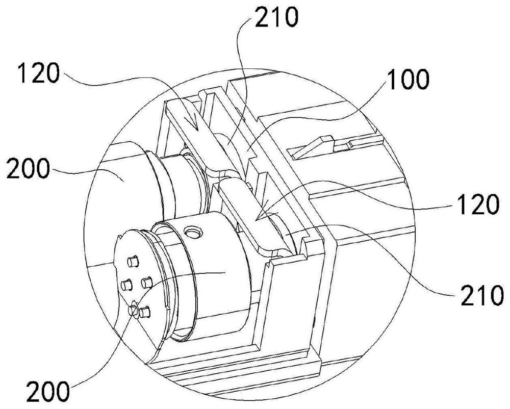
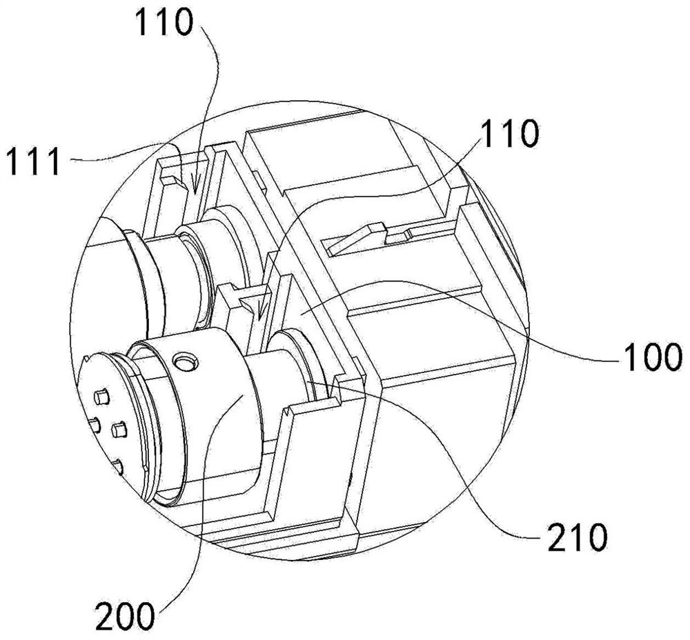
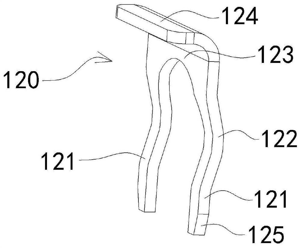
[0046] Please refer to Figure 1 to Figure 4 As shown, the embodiment of the present invention discloses an optical module structure. The disclosed optical module structure includes a base 100 for installing an optoelectronic device 200, and the installation part is provided with an elastic abutment part 120, and the flange of the optoelectronic device 200 The portion 210 is attached to the end surface of the base 100 under the elastic force of the elastic contact portion 120 .
[0047]Wherein, through the elastic abutting portion 120 provided on the base 100, after the joint end of the optoelectronic device 200 is inserted into the through hole of the base 100, the flange portion 210 can be placed between the elastic abutting portion 120 and the base. 100, and through the mutual pressing between the flange part 210 and the elastic abutment part 120, the elastic abutment part 120 produces an applicable elastic deformation, so that the flange part 210 is under the elastic force...
Embodiment 2
[0056] Please refer to Figure 5 and Figure 6 As shown, the embodiment of the present invention discloses a shielding assembly. The disclosed shielding assembly includes a mounting part 300 and an elastic piece 310; the mounting part 300 is an annular structural member with an opening 301; The other edge of the installation part 300 away from the elastic piece 310 is provided with an inwardly folded first flange structure 302 .
[0057] Wherein, the mounting part 300 provided with the opening 301 makes the two sides of the mounting part 300 form an elastic clamping structure with free ends, and when the mounting part 300 is assembled with the housing of the optical module, the two sides of the mounting part 300 can be Stretch out so that it is convenient to be sleeved at the desired position, and after the mounting part 300 is set at the desired position, the two side parts of the mounting part 300 are clamped and hugged on the housing by elastic restoring force, so that the...
Embodiment 3
[0067] The embodiment of the present invention discloses an optical module structure, and the disclosed optical module structure may include a casing and the shielding assembly described in Embodiment 2; wherein, the inside of the casing is provided with a type for mounting a PCB board and an optoelectronic device. The cavity 405 provides a bearing base for the installation of the PCB board and optoelectronic devices, and takes into account the appearance performance.
[0068] Among them, such as Figure 8 , Figure 9 and Figure 10 As shown, the housing is provided with a card slot 401 adapted to the first flange structure 302, the mounting part 300 is hugged on the housing, and the first flange structure 302 is embedded in the card slot 401, thereby passing through the card slot 401 The structure enables the housing to be embedded and fitted with the first flange structure 302 of the mounting part 300 of the shielding assembly, which not only can limit the positioning of t...
PUM
 Abstract
Description
Claims
Application Information
 - Generate Ideas
- Intellectual Property
- Life Sciences
- Materials
- Tech Scout
- Unparalleled Data Quality
- Higher Quality Content
- 60% Fewer Hallucinations
Browse by: Latest US Patents, China's latest patents, Technical Efficacy Thesaurus, Application Domain, Technology Topic, Popular Technical Reports.
© 2025 PatSnap. All rights reserved.Legal|Privacy policy|Modern Slavery Act Transparency Statement|Sitemap|About US| Contact US: help@patsnap.com