Micro rotary locking device

A locking device and locking technology, applied in the direction of coupling device, parts of connecting device, electrical components, etc., can solve the problems of heavy weight, large packaging size of locking mechanism, redundant steps, etc., and achieve small occupation size and structure. Ingenious, easy-to-use effects

Active Publication Date: 2021-04-06
CHINA AVIATION OPTICAL-ELECTRICAL TECH CO LTD
View PDF11 Cites 3 Cited by
  • Summary
  • Abstract
  • Description
  • Claims
  • Application Information

AI Technical Summary

Problems solved by technology

[0003] The purpose of the present invention is to solve the technical problems in the prior art that the locking mechanism has a large package size, heavy weight and redundant steps during operation due to the addition of expansion buckles, thereby proposing a miniaturized rotary locking device

Method used


Image

  • Micro rotary locking device
  • Micro rotary locking device
  • Micro rotary locking device

Examples


Embodiment Construction

[0024] Further detailed description will be made below in conjunction with the accompanying drawings and preferred embodiments.

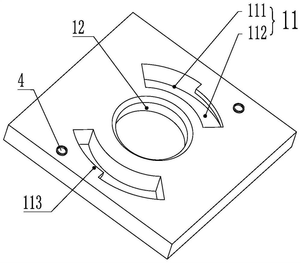
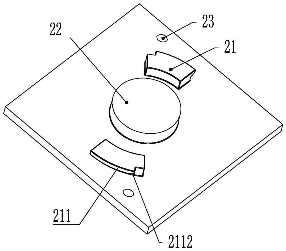
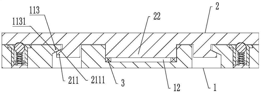
[0025] An embodiment of a miniaturized rotary locking device of the present invention is Figure 1 to Figure 4 As shown, a miniaturized rotary locking device includes a locking fixed end 1 and a rotating movable end 2 that are engaged in relative rotation to achieve mutual locking, with the locking mating ends of the locking fixed end and the rotating movable end as their respective front ends; At least one swivel groove 11 is provided on the locking fixed end, and the swivel groove 11 is an arc-shaped groove. Preferably, there are two swivel grooves arranged symmetrically on both sides of the locking fixed end, so as to achieve a stable locking fit relationship The screwing groove includes a connected initial section 111 and a locking section 112. The inner wall of the front end of the locking section 112 has a stopper 113 extending toward the inne...


PUM


Abstract

The invention relates to a micro rotary locking device. The device comprises a locking fixed end and a rotary movable end which are rotationally buckled to achieve mutual locking, wherein a rotary matching groove is formed in the locking fixed end, the rotary matching groove comprises a starting section and a locking section which communicate with each other, and the front end of the locking section is provided with a stopping part extending towards the interior of the locking section; an elastic sealing unit is arranged in a mounting groove formed in the locking fixing end; the rotary movable end is provided with a rotary fit key in rotary fit with the rotary fit groove and a protruding part corresponding to the installation groove, and the rotary fit key is provided with a locking part in stop fit with the stop part in the front-back direction. In the locking state, the elastic sealing unit provides elastic force for the protruding part so that the locking part can abut against the blocking part, the locking fixed end and the rotating movable end can be locked in the front-back direction, rapid assembling and disassembling of the locking fixed end and the rotating movable end can be achieved, operation is convenient, and practicability is high. Rapid sealing and fixed connection of various parts can be realized, and related functions of the electrical connection assembly can be further realized.

Description

technical field [0001] The invention belongs to the technical field of locking structures, in particular to a miniaturized rotary locking device. Background technique [0002] Most of the locking mechanisms in the prior art are fixed by spring compression or expansion buckles. During the operation, the spring mechanism or the expansion buckle mechanism needs to be unlocked first to realize removal and removal, resulting in cumbersome operation and low quick release efficiency. For example, in the field of connector technology, the interconnection between insulators can realize the fixing of the contacts installed on them. The connection methods between insulators include bonding, thread or buckle structure; plugs and sockets can also be locked through some locking structures. Carry out head-seat locking fit, for example, the light and / or electrical signal conduction of the internal contacts after the head-seat mechanical connection is realized through threaded connection, sn...

Claims


Application Information

Patent Timeline
Patent Type & Authority Applications(China)
IPC IPC(8): H01R13/627H01R13/629H01R13/639H01R13/52
CPCH01R13/627H01R13/629H01R13/639H01R13/52
Inventor 黄锦源周超殷向阳张新建
Owner CHINA AVIATION OPTICAL-ELECTRICAL TECH CO LTD
Why Eureka
Try Eureka