
Semi-finished complete denture based on manufactured artificial dentition structure and rapid manufacturing method of complete denture

A technology for prefabricated dentition and complete denture is applied in the field of rapid production of complete dentures, and can solve the problems of not being able to be achieved at one time, numerous procedures, and long time-consuming.

Active Publication Date: 2021-04-09
吴瑛
View PDF16 Cites 0 Cited by
  • Summary
  • Abstract
  • Description
  • Claims
  • Application Information

AI Technical Summary

Problems solved by technology

[0008] However, in clinical practice, most patients often cannot achieve the occlusal position of the upper and lower teeth at one time and satisfy the patient's facial aesthetics. It is often necessary to go back and forth between the clinical clinic and the denture processing factory repeatedly to re-upper the jaw frame and re-fit the denture. Arrange the teeth, try them repeatedly until the occlusal relationship is correct, and the shape of the dentures satisfies the patient, then the filling and grinding can be completed
The entire process takes several days, and the process is numerous and time-consuming

Method used


Image

  • Semi-finished complete denture based on manufactured artificial dentition structure and rapid manufacturing method of complete denture
  • Semi-finished complete denture based on manufactured artificial dentition structure and rapid manufacturing method of complete denture
  • Semi-finished complete denture based on manufactured artificial dentition structure and rapid manufacturing method of complete denture

Examples


Embodiment Construction

[0034] The present application will be described in further detail below in conjunction with the accompanying drawings and embodiments. It should be understood that these examples are only used to more fully explain the features of the present application, rather than limit the claims of the present application.

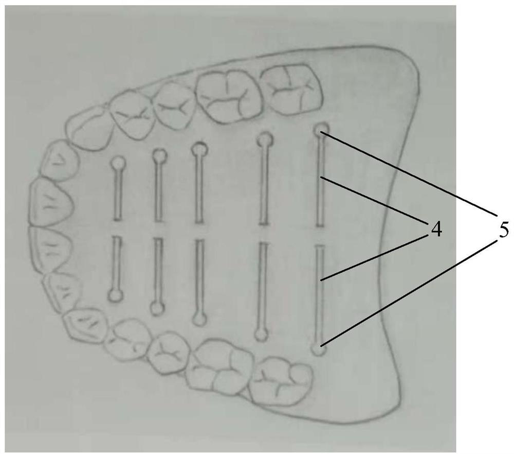
[0035] Such as Figure 3 to Figure 5 As shown, this embodiment adopts a semi-finished complete denture based on the preformed dentition structure, which includes a preformed temporary base and a preformed dentition fixedly combined on the preformed temporary base; the preformed temporary base The thickness is 2-3mm, using the same thermosetting resin material as the clinical complete denture base.

[0036] The palatal surface, buccal surface, and lip surface of the preformed temporary base of the upper jaw and the lingual, buccal, and labial surfaces of the preformed temporary base of the mandible are all provided with multiple strips from the polished surface of th...


PUM

PropertyMeasurementUnit
Diameteraaaaaaaaaa
Thicknessaaaaaaaaaa

Abstract

The invention provides a semi-finished complete denture based on a manufactured artificial dentition structure and a rapid manufacturing method of the complete denture, and aims to reduce the workload of dentists and technicians and shorten the waiting time of patients on the premise of accurately adapting to the patients. The semi-finished complete denture comprises a pre-formed temporary base plate made of a thermosetting resin material and a manufactured artificial dentition fixedly combined with the pre-formed temporary base plate, the pre-formed temporary base plate is provided with a plurality of strip-shaped holes, and the orifice width of one side of the polished surface is slightly larger than that of one side of the tissue surface; the strip-shaped holes located in the palate surface area of the maxillary pre-formed temporary base plate are distributed in a bilateral symmetry mode, and the two ends of each strip-shaped hole in the length direction are closed; the ends, located in the length direction, of part or all of the strip-shaped holes in other areas reach the edge of the pre-formed temporary base plate to form an opening of the edge of the pre-formed temporary base plate, and the other end of each strip-shaped hole is closed; and the lip-palate (tongue) distance and the buccal-palate (tongue) distance of tissue surface of the temporary base plate are slightly larger than the distance between the corresponding parts of the tissue surface of the clinical complete denture, so that the effect of an impression tray is replaced, and the space of an impression material is reserved.

Description

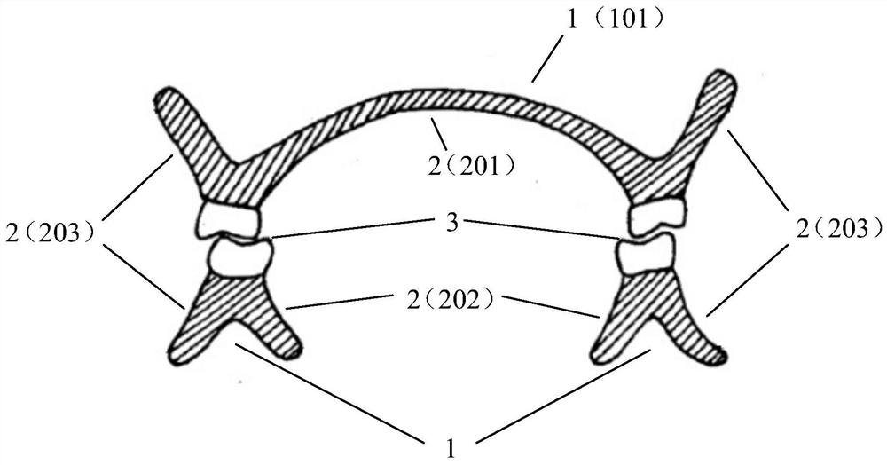
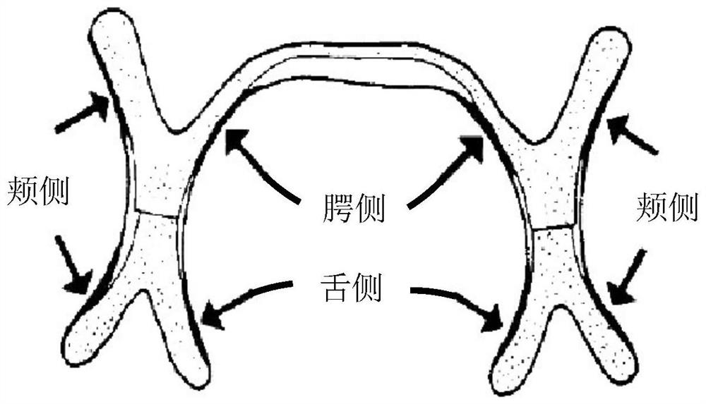
technical field [0001] The invention relates to a rapid manufacturing method of complete dentures. Background technique [0002] Such as figure 1 As shown, the surface structure of a complete denture can be divided into three parts, namely tissue surface 1, polished surface 2 and occlusal surface 3. [0003] The tissue surface is the surface that the denture base is in close contact with the tissues such as the alveolar ridge and the palate. The tissue area covered by the base is called the denture bearing area (Denture Bearing Area), and the load borne by the denture during function is transmitted to the supporting tissue through the tissue surface. The tissue surface is also the main site for dentures to be retained. [0004] Polishing Surface, also known as polished surface, is the surface where the denture is in contact with the soft tissues and muscles of the lips, cheeks, and tongue, such as figure 2 shown. The polished surface should form an appropriate concave ...

Claims


Application Information

Patent Timeline
IPC IPC(8): A61C13/08A61C9/00
CPCA61C13/08A61C13/081A61C9/00
Inventor 吴瑛刘改丽张存莉吴洋吴庚林
Owner 吴瑛
Learn More