Spine traction bed for medical orthopedics department patient with leg discomfort

A traction bed and leg technology, applied in the field of spinal traction bed, can solve the problems of increasing leg discomfort, inability to use effectively, discomfort and the like

Pending Publication Date: 2021-04-09
叶柏成
View PDF28 Cites 0 Cited by
  • Summary
  • Abstract
  • Description
  • Claims
  • Application Information

AI Technical Summary

Problems solved by technology

[0003] At present, the traction bed used for self-operation of the patient in the traction bed drives the traction of the spine by lifting the patient's feet like riding a bicycle, but this method for a long time cannot be effective for patients with leg discomfort. It increases the discomfort of the legs when it is self-tracting. At the same time, because there is a fixed bed board and a movable bed board in the traction bed, and the movable bed board moves to the fixed bed board, there must be a certain distance between the movable bed board and the fixed bed board. , and this distance causes the patient’s part of the body to be in a suspended state when lying down, which further leads to the discomfort of the patient who uses the leg discomfort when performing self-traction. Therefore, we propose a medical orthopedic leg Spinal traction bed for unwell patients

Method used


Image

  • Spine traction bed for medical orthopedics department patient with leg discomfort
  • Spine traction bed for medical orthopedics department patient with leg discomfort
  • Spine traction bed for medical orthopedics department patient with leg discomfort

Examples


Embodiment Construction

[0024] The following will clearly and completely describe the technical solutions in the embodiments of the present invention with reference to the accompanying drawings in the embodiments of the present invention. Obviously, the described embodiments are only some, not all, embodiments of the present invention. Based on the embodiments of the present invention, all other embodiments obtained by persons of ordinary skill in the art without making creative efforts belong to the protection scope of the present invention.

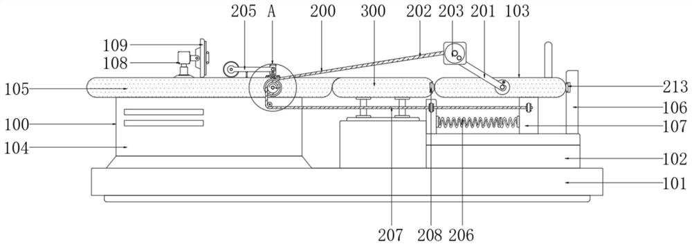
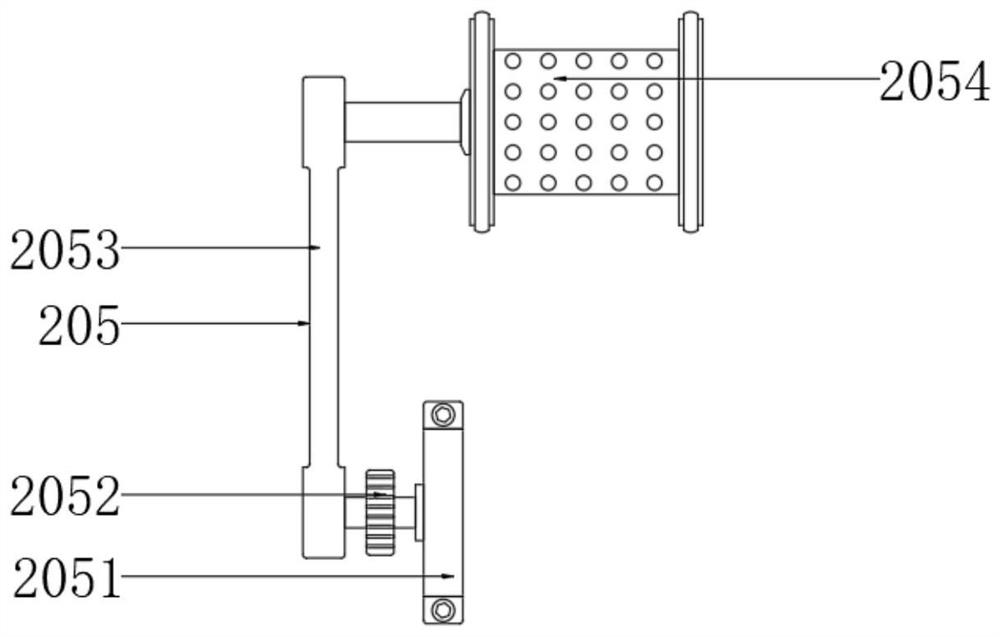
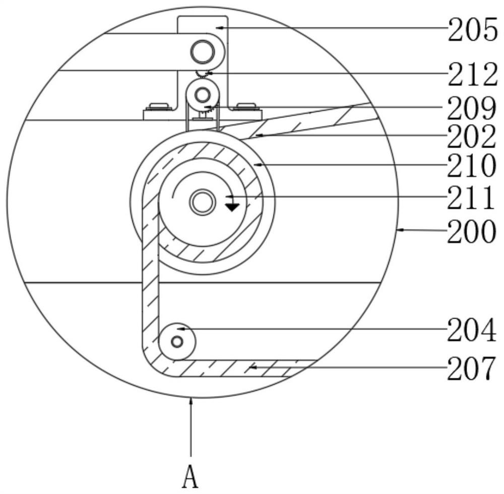
[0025] see Figure 1-4 , the present invention provides a spinal traction bed for patients with leg discomfort in orthopedics, including a bed frame body 100, including a base 101, and the left and right sides of the top of the base 101 are respectively fixedly provided with a support seat 2 104 and a support seat 102 , a movable bed board 103 is arranged above the support seat one 102, a fixed bed board 105 is fixedly arranged on the top of the support seat t...


PUM


Abstract

The invention discloses a spine traction bed for a medical orthopedics department patient with leg discomfort, and belongs to the technical field of spine traction beds. The spine traction bed comprises a bed frame main body, a leg and spine traction linkage assembly and an auxiliary bed plate; the bed frame main body comprises a base; a supporting seat II and a supporting seat I are fixedly arranged on the left side and the right side of the top of the base respectively; a movable bed plate is arranged above the supporting seat I; a fixed bed plate is fixedly arranged at the top of the supporting seat II; the leg and spine traction linkage assembly comprises rocker arms rotationally arranged on the front side and the rear side of the movable bed plate, and connecting shells are fixedly arranged at the other ends of the two sets of rocker arms; and the auxiliary bed plate is arranged between the movable bed plate and the fixed bed plate. By arranging the leg and spine traction linkage assembly, a patient can rotate a driving hand wheel with two hands, on one hand, discomfort of the leg patient in use is reduced, the patient can perform traction by himself / herself, on the other hand, the legs of the patient can be effectively exercised and relieved, and the legs and the spine of the patient can be better recovered.

Description

technical field [0001] The invention relates to the technical field of spinal traction beds, in particular to a spinal traction bed for treating orthopedic patients with unwell legs. Background technique [0002] Medical treatment refers to the treatment of diseases. Orthopedics mainly studies the anatomy, physiology and pathology of the musculoskeletal system, and uses drugs, surgery and physical methods to maintain and develop. When treating orthopedic patients with spinal problems, doctors often use traction beds to traction the spine of orthopedic patients. [0003] At present, the traction bed used for self-operation of the patient in the traction bed drives the traction of the spine by lifting the patient's feet like riding a bicycle, but this method for a long time cannot be effective for patients with leg discomfort. It increases the discomfort of the legs when it is self-tracting. At the same time, because there is a fixed bed board and a movable bed board in the t...

Claims


Application Information

Patent Timeline
Patent Type & Authority Applications(China)
IPC IPC(8): A61F5/042A61H1/02A61H15/00
CPCA61F5/042A61H15/0078A61H1/0237A61H1/0218A61H2015/0014A61H2201/1207A61H2205/10A61H2201/0142
Inventor 叶柏成
Owner 叶柏成
Why Eureka
Try Eureka