
Conveying mechanism for flour production

A conveying mechanism and flour technology, which is applied in the direction of dryer, magnetic separation, solid separation, etc., can solve the problems of lower product quality, easy clogging of dragons, and many iron impurities in flour, so as to prevent clogging and increase the discharge effect Effect

Pending Publication Date: 2021-04-09
安徽正宇面粉有限公司
View PDF12 Cites 0 Cited by
  • Summary
  • Abstract
  • Description
  • Claims
  • Application Information

AI Technical Summary

Problems solved by technology

[0005] Flour conveying equipment in the prior art generally uses conveyor belts or conventional dragons for transportation. However, the traditional conveying equipment firstly has its dragons that are easy to block, or there will be a lot of iron impurities in the flour, resulting in its products. A reduction in quality occurs

Method used


Image

  • Conveying mechanism for flour production
  • Conveying mechanism for flour production
  • Conveying mechanism for flour production

Examples


Embodiment 1

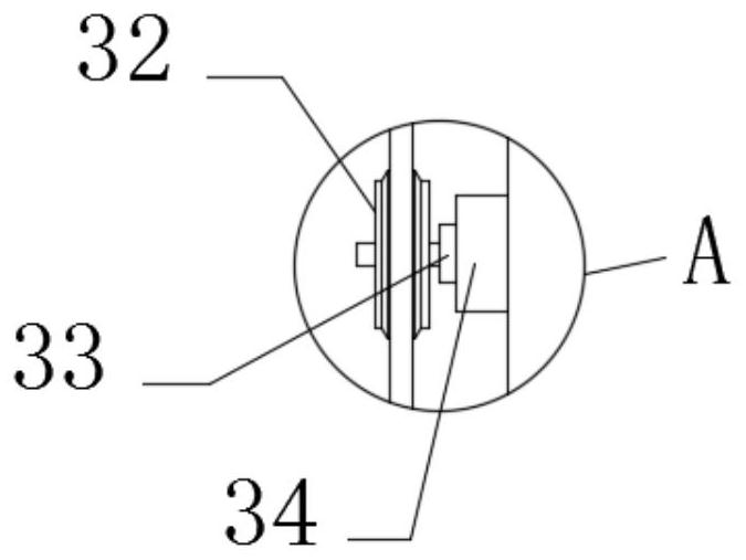
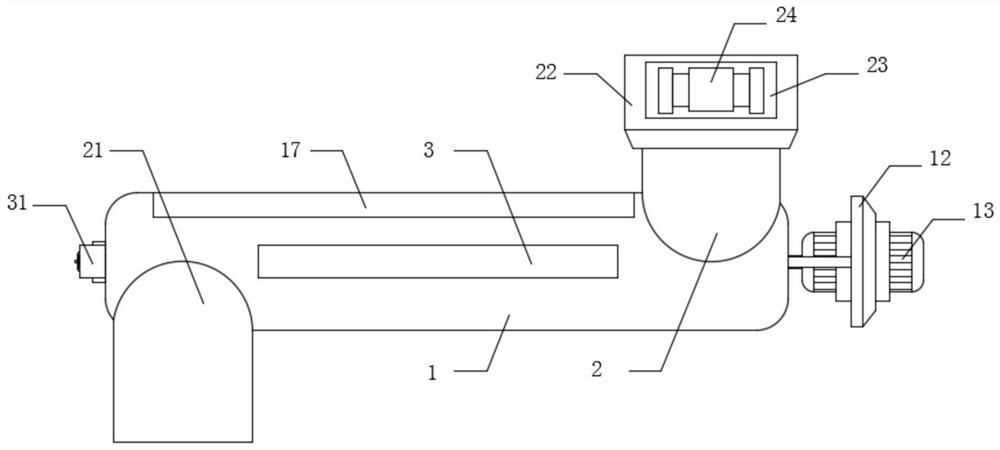
[0028] Please refer to figure 1 , figure 2 , image 3 and Figure 4 ,in, figure 1 It is a schematic diagram of a half-section top view of the main body of the present invention; figure 2 for the present invention figure 1 Schematic diagram of enlarged structure of area A; image 3 It is a schematic structural diagram of the overall front view of the present invention; Figure 4 It is a schematic view of the top view structure of the screening frame of the present invention; specifically, a conveying mechanism for flour production, comprising: a main body 1, two connecting rods 11 are welded at one end of the main body 1, and one end of the connecting rod 11 is connected by a bolt A motor bracket 12 is installed, and a motor 13 is mounted on the motor bracket 12 through bolts. The power output end of the motor 13 penetrates the main body 1 and is welded with a first magnetic rod 14 and a second magnetic rod 15. The magnetic rod 14 and the second magnetic rod 15 are mut...

Embodiment 2

[0039] Please refer to figure 1 , figure 2 , image 3 and Figure 4 ,in, figure 1 It is a schematic diagram of the overall front view half-section structure of the present invention; figure 2 for the present invention figure 1 Schematic diagram of enlarged structure of area A; image 3 It is a schematic structural diagram of the overall front view of the present invention; Figure 4 It is a schematic view of the top view structure of the screening frame of the present invention; specifically, a conveying mechanism for flour production, comprising: a main body 1, two connecting rods 11 are welded at one end of the main body 1, and one end of the connecting rod 11 is connected by a bolt A motor bracket 12 is installed, and a motor 13 is mounted on the motor bracket 12 through bolts. The power output end of the motor 13 penetrates the main body 1 and is welded with a first magnetic rod 14 and a second magnetic rod 15. The magnetic rod 14 and the second magnetic rod 15 are ...


PUM


Abstract

One or more embodiments of the invention provide a conveying mechanism for flour production, and the conveying mechanism comprises a main body, two connecting rods are welded at one end of the main body, a motor bracket is mounted at one ends of the connecting rods through a bolt, a motor is mounted on the motor bracket through a bolt, the power output end of the motor penetrates through the main body and is welded with a first magnetic rod and a second magnetic rod, and the splicing part of the first magnetic rod and the second magnetic rod is hollow; through the arrangement of a screening frame during use, injected flour can be conveniently vibrated and screened during use, and the problem that the quality of the flour is affected due to the fact that a large number of iron residues are left in the flour is solved; through the arrangement of an aeration frame and an aeration pump, the internal discharging effect is effectively and greatly improved in the use process, the blockage condition is prevented, through the arrangement of an electric heating rod, the internal drying effect is achieved, and in addition, the flour condensation condition is reduced in the drying state.

Description

technical field [0001] One or more embodiments of this specification relate to the technical field of flour conveying, in particular to a conveying mechanism for flour production. Background technique [0002] Flour is a powder made from wheat. According to the protein content in flour, it can be divided into high-gluten flour, medium-gluten flour, low-gluten flour and gluten-free flour. [0003] The "flour" we often say refers to wheat flour, that is, flour that is ground from wheat, and names such as "high-gluten wheat flour" refer to what we usually call flour. Wheat flour is divided into special flour (such as bread flour, dumpling flour, biscuit flour, etc.), general-purpose flour (such as standard flour, rich flour), nutritionally fortified flour (such as calcium-enriched flour, iron-rich flour, "7+1 "Nutrition-fortified flour, etc.); according to the precision, it is divided into special first-class flour, special second-class flour, standard flour, ordinary flour, ...

Claims


Application Information

Patent Timeline
IPC IPC(8): B03C1/30B03C1/28F26B23/04
CPCB03C1/30B03C1/28F26B23/04
Inventor 张文占曹广领曹恒瑞
Owner 安徽正宇面粉有限公司
Learn More