Supercharge Your Innovation With Domain-Expert AI Agents!

Glue spraying method for light holes of cigarette rod shell

A light-transmitting hole and glue-spraying technology, applied in the field of electronic cigarettes, can solve problems such as inability to prevent dust, uneven surface, and insufficient sealant pressure

Active Publication Date: 2021-04-09
SHENZHEN EVERWIN PRECISION TECH
View PDF5 Cites 0 Cited by
  • Summary
  • Abstract
  • Description
  • Claims
  • Application Information

AI Technical Summary

Problems solved by technology

The existing ones are generally relatively simple, such as setting an LED light hole, etc., and the LED light is directly enclosed in the light hole, but there is always a gap between the edge of the light hole and the LED light, and it cannot be dustproof. etc. effect
Existing sealing generally adopts the method of dispensing glue, and uses the natural flow of glue to fill the light-transmitting gaps, etc. However, the dispensing method has problems such as insufficient sealant pressure, resulting in uneven surfaces, etc.

Method used


Image

  • Glue spraying method for light holes of cigarette rod shell
  • Glue spraying method for light holes of cigarette rod shell
  • Glue spraying method for light holes of cigarette rod shell

Examples


Embodiment 1

[0041] In this embodiment, the glue spraying method for the light-transmitting hole of the cigarette rod housing includes the following steps:

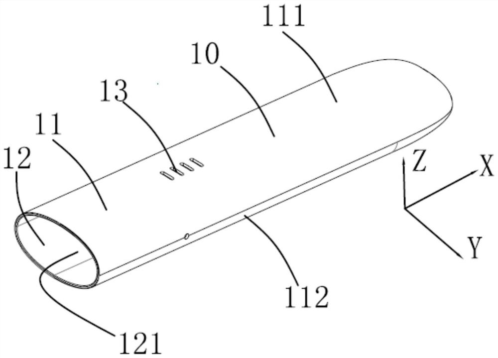
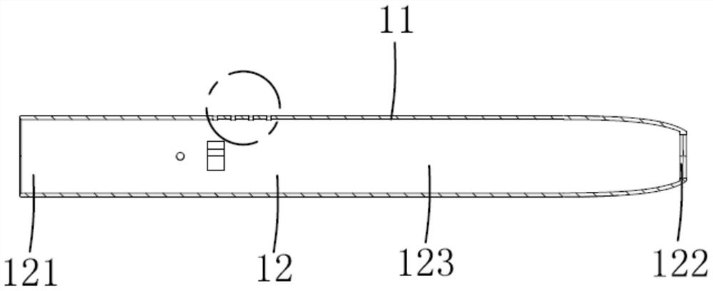
[0042] S10, the cigarette rod housing 10 is set outside the rod body 221 of the jig 20 and placed on the workbench of the glue spraying machine;

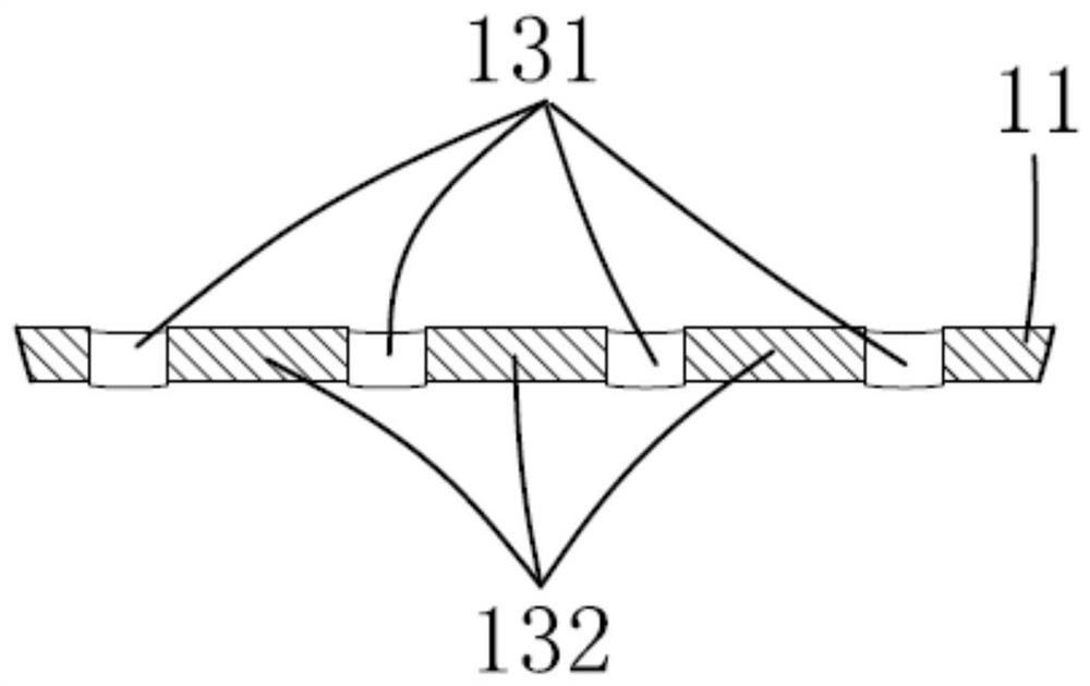
[0043] The glue spraying machine in this step includes a positioning unit, a glue spraying head, a heating device, a processing unit, and the like. The inner surface of the light transmission hole 131 of the cigarette rod housing 10 is closed by the outer surface of the support rod 22 of the fixture 20. The positioning unit is combined with the glue spraying head, and the positioning unit determines the accurate starting position of glue spraying by taking pictures in advance.

[0044] S20, the positioning unit of the glue spraying machine moves to determine the glue spraying starting position of the light transmission hole 131 of the cigarette rod housing 10, and moves the glue spraying h...

Embodiment 2

[0056] In this embodiment, the glue spraying method for the light-transmitting hole of the cigarette rod housing includes the following steps:

[0057] S10, the cigarette rod housing 10 is set outside the rod body 221 of the jig 20 and placed on the workbench of the glue spraying machine;

[0058] The glue spraying machine in this step includes a positioning unit, a glue spraying head, a heating device, a processing unit, and the like. The inner surface of the light transmission hole 131 of the cigarette rod housing 10 is closed by the outer surface of the support rod 22 of the fixture 20. The positioning unit is combined with the glue spraying head, and the positioning unit determines the accurate starting position of glue spraying by taking pictures in advance.

[0059] S20, the positioning unit of the glue spraying machine moves to determine the glue spraying starting position of the light transmission hole 131 of the cigarette rod housing 10, and moves the glue spraying h...


PUM

PropertyMeasurementUnit
Widthaaaaaaaaaa

Abstract

The invention discloses a glue spraying method for light holes of a cigarette rod shell. The cigarette rod shell comprises a shell wall, a cavity defined by the shell wall and provided with an opening in at least one end and the multiple light holes formed in the shell wall in the transverse direction. The glue spraying method comprises the following steps that S10, a jig is provided, and the jig is sleeved with the cigarette rod shell and placed on a workbench of a glue spraying machine; the glue spraying machine comprises a glue spraying head, a positioning unit and a processing unit; S20, the glue spraying head is moved to the position above the starting position; S30, the glue spraying head and the light hole move relatively in the transverse direction, and the heated glue is sprayed into the light hole till glue spraying of the current light hole is completed; S40, the glue spraying head moves to the next light hole, and S30 is repeated to complete glue spraying operation of one light hole until glue spraying of all the light holes is completed; and S50, the glue on the cigarette rod shell sprayed with the glue is cured through blue light irradiation equipment. The glue sprayed into the light holes is smooth and good in light transmittance.

Description

technical field [0001] The invention relates to the field of electronic cigarettes, in particular to a glue spraying method for a light-transmitting hole of a cigarette rod shell. Background technique [0002] Atomized electronic cigarettes generally include a cigarette rod and a pod matched with the device. The device generally includes a metal casing, a battery assembled in the metal casing, a processing unit, and a circuit. E-liquid is stored and heated and atomized through the tobacco rod. Existing e-cigarette users have higher and higher requirements for the function and taste of the e-cigarette. The metal shell of the cigarette rod is generally equipped with a light-transmitting hole structure, and the current status of the e-cigarette is displayed through the combination of different cursors. The existing ones are generally relatively simple, such as setting an LED light hole, etc., and the LED light is directly enclosed in the light hole, but there is always a gap b...

Claims


Application Information

Patent Timeline
IPC IPC(8): B05D1/02B05D3/06A24F40/40B05B13/02B05B13/04B05B15/68
CPCB05D1/02B05D3/06A24F40/40B05B13/041B05B13/0221B05B15/68
Inventor 钟发志张国平
Owner SHENZHEN EVERWIN PRECISION TECH
Features
  • R&D
  • Intellectual Property
  • Life Sciences
  • Materials
  • Tech Scout
  • Unparalleled Data Quality
  • Higher Quality Content
  • 60% Fewer Hallucinations
Learn More