
Angle-adjustable locating tool for automobile axle housing machining and locating process

A positioning tool and adjustable technology, applied in positioning devices, metal processing equipment, metal processing machinery parts, etc., can solve the problems of rear axle half shaft stuck, low processing efficiency, difficult to ensure the coaxiality of the transition joints at both ends, etc. , to achieve the effect of ensuring the processing progress, improving production efficiency and shortening the production cycle

Inactive Publication Date: 2021-04-09
ANHUI ZHONGGONG TECH
View PDF9 Cites 0 Cited by
  • Summary
  • Abstract
  • Description
  • Claims
  • Application Information

AI Technical Summary

Problems solved by technology

[0003] At present, when processing the axle housing, it is necessary to use positioning work. However, traditional tooling cannot complete the processing of multiple end milling surfaces in the case of one workpiece clamping and clamping, which makes the processing time-consuming and low-efficiency. In addition, the current processing method used in the same industry is: double-headed horizontal processing to process the size of the transition plate at both ends, and then use the transition plate at both ends It is difficult to ensure the coaxiality of the transition joints at both ends with this processing method, and there is a deviation in the distance between the ABS surface at both ends and the center of the axle housing, which will cause rear Hidden danger of the axle shaft being stuck

Method used


Image

  • Angle-adjustable locating tool for automobile axle housing machining and locating process
  • Angle-adjustable locating tool for automobile axle housing machining and locating process
  • Angle-adjustable locating tool for automobile axle housing machining and locating process

Examples


Embodiment Construction

[0026] The following will clearly and completely describe the technical solutions in the embodiments of the present invention with reference to the accompanying drawings in the embodiments of the present invention. Obviously, the described embodiments are only some, not all, embodiments of the present invention.

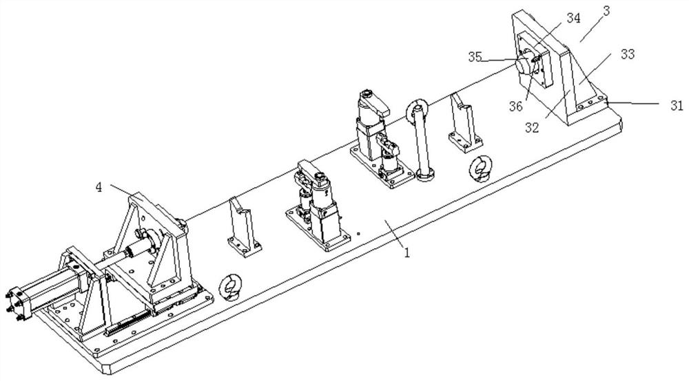
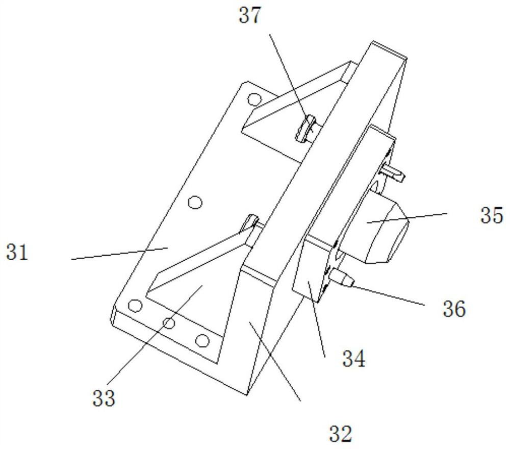
[0027] refer to Figure 1-7 , an angle-adjustable positioning tool for automobile axle housing processing, including a fixed tool 1 for fixing the axle housing body 2, the two ends of the axle housing body 2 are connected with transition adapters 21, and one end of the fixed tool 1 is fixed with a first The positioning mechanism 3, the other end of the fixed tooling 1 is equipped with a second positioning mechanism 4 that can move laterally, the structure of the first positioning mechanism 3 and the second positioning mechanism 4 is the same, the first positioning mechanism 3 includes a fixed tooling 1 Bottom plate 31, the top of bottom plate 31 is integrally provide...


PUM


Abstract

The invention discloses an angle-adjustable locating tool for automobile axle housing machining and an locating process. The locating tool comprises a fixing tool body used for fixing an axle housing body, wherein the two ends of the axle housing body are each connected with a transition connecting disc, a first locating mechanism is fixed to one end of the fixing tool body, a second locating mechanism capable of moving transversely is mounted at the other end of the fixing tool body, the first locating mechanism and the second locating mechanism are the same in structure, the first locating mechanism comprises a bottom plate fixed to the fixing tool body, a vertical plate in the vertical direction is integrally arranged at the top of each bottom plate, an angle plate is fixed between one side of each vertical plate and the corresponding transition connecting disc, a locating pin is arranged at the side, away from the corresponding angle plate, of each vertical plate, a locating pin rotating shaft is arranged on each locating pin, and a locating plate is rotationally mounted on each locating pin rotating shaft. According to the scheme, machining of multiple vertical milling faces can be completed under the condition that a workpiece is clamped at a time, so that the machining progress of a product is guaranteed, the production takt is shortened, and the production efficiency is improved.

Description

technical field [0001] The invention relates to the field of production tooling for auto parts, in particular to an angle-adjustable positioning tool for processing automobile axle housings and a positioning process. Background technique [0002] The axle housing is the base for installing the main reducer, differential, half shaft and wheel assembly. Its main function is to support and protect the main reducer, differential and half shaft. Generally speaking, the ordinary non-disconnected drive axle housing is a rigid hollow beam supported on the left and right driving wheels, and the transmission parts such as the final reducer, differential, and half shafts are all installed in it. Longitudinal leaf springs are connected with the frame or compartment. It is an important part of the drive axle and one of the main components of the driving system. The drive axle housing should have sufficient strength and rigidity, low mass, and facilitate the disassembly and adjustment o...

Claims


Application Information

Patent Timeline
Patent Type & Authority Applications(China)
IPC IPC(8): B23Q3/06B23Q1/25
CPCB23Q1/25B23Q3/06B23Q3/062
Inventor 齐咏
Owner ANHUI ZHONGGONG TECH
Learn More