Fastening assistive device for screws in semi-closed space of small-sized table body
A semi-enclosed, platform-based technology, applied to screwdrivers, manufacturing tools, wrenches, etc., can solve the problems of being unable to rotate the fastening screw with the handle of the screwdriver, the space above the screw head is narrow, and the complete fastening cannot be achieved, etc., to achieve shortening The effect of production cycle, simplification of installation and maintenance, improvement of quality and production efficiency
- Summary
- Abstract
- Description
- Claims
- Application Information
AI Technical Summary
Problems solved by technology
Method used
Image

Examples
Embodiment Construction
[0020] Attached below Figure 1-2 An embodiment of the present invention is described so as to clearly and completely describe the technical solution. Obviously, the described embodiment is only a part of the embodiments of the present invention, rather than all the embodiments.
[0021] In describing the present invention, it should be understood that the terms "upper", "lower", "front", "rear", "left", "right", "top", "bottom", "inner", " The orientation or positional relationship indicated by "outside", etc. is based on the orientation or positional relationship shown in the drawings, which is only for the convenience of describing the present invention and simplifying the description, rather than indicating or implying that the referred device or element must have a specific orientation, so as to Specific orientation configurations and operations, therefore, are not to be construed as limitations of the invention.
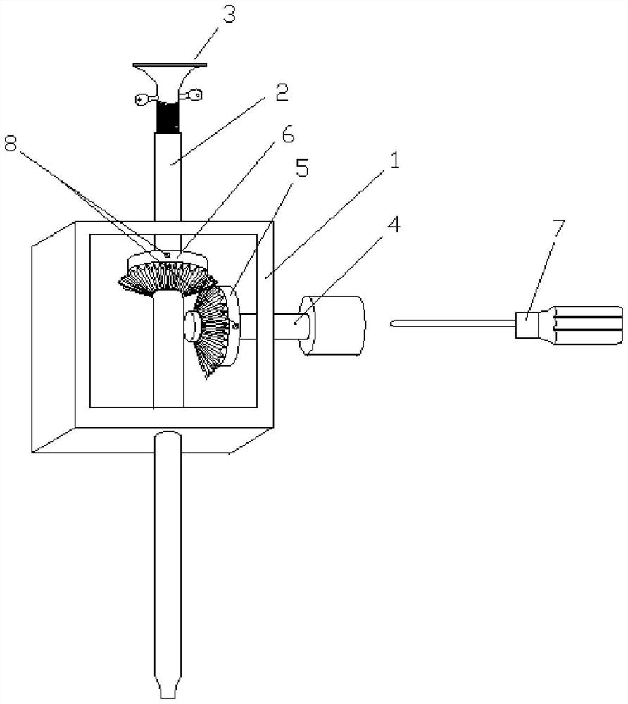
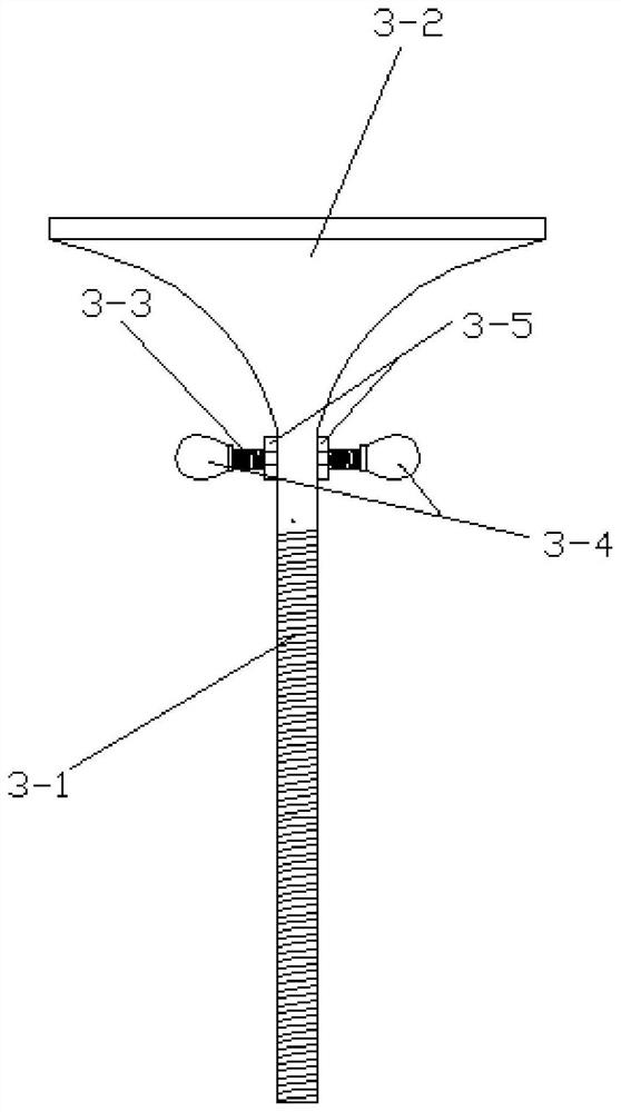
[0022] Fastening aids for screws in small table semi-enc...
PUM
 Abstract
Description
Claims
Application Information