Robot with moving function

A mobile function, robot technology, applied in the field of robots, can solve problems such as affecting the normal work of robots

Active Publication Date: 2021-04-09
中国南方电网有限责任公司超高压输电公司柳州局
View PDF9 Cites 1 Cited by
  • Summary
  • Abstract
  • Description
  • Claims
  • Application Information

AI Technical Summary

Problems solved by technology

[0003] However, it is inevitable that the robot will pass through the uneven bottom surface in the process of moving. In this case, the robot will inevitably vibrate to various degrees, which will affect th

Method used


Image

  • Robot with moving function
  • Robot with moving function
  • Robot with moving function

Examples


Embodiment 1

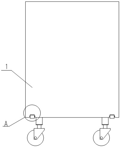
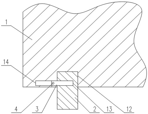
[0033] A robot with a moving function, comprising a robot body 1 and a moving device installed on the bottom of the robot body 1, the moving device includes several universal wheels, and the universal wheels are connected to the bottom surface of the robot body 1 through a connecting assembly, The connection assembly includes a support block 2, a limit plate 3, a control rod 4, a movable plate 5 and a connection block 6;

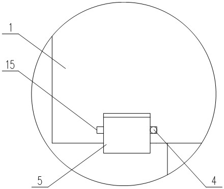
[0034] The bottom surface of the robot body 1 is provided with a fixed hole 12, the axis of the fixed hole 12 is perpendicular to the ground, the top of the support block 2 cooperates with the fixed hole 12, and the side of the support block 2 is provided with a matching hole 13, so The axis of the matching hole 13 is parallel to the ground, and the hole wall of the fixing hole 12 is provided with a limiting hole 14. The axis of the limiting hole 14 is coaxial with the axis of the fixing hole 12. One end of the limiting plate 3 is connected to the Fitting ho...

Embodiment 2

[0039] A specific implementation description is made for the operation mode in Embodiment 1.

[0040] Such as figure 2 As shown, in the present invention, anti-slip lines are provided on the surface of the control rod 4, which can increase the friction of the control rod 4 and prevent the user from losing his hand when the control rod 4 is exerted force.


PUM


Abstract

The invention provides a robot with a moving function. A moving device comprises a plurality of universal wheels, a fixing hole is formed in the bottom face of a robot body, the top of a supporting block is matched with the fixing hole, a matching hole is formed in the side face of the supporting block, a limiting hole is formed in the hole wall of the fixing hole, one end of a limiting plate is matched with the matching hole, the other end is matched with the limiting hole. a movable groove is formed in the side face of the robot body, one end of the control rod penetrates through the movable groove and then is connected with the limiting plate, the top of the movable plate is hinged to the side face of the robot body, a mounting hole is formed in the bottom face of the supporting block, and a guide groove is formed in the hole wall of the mounting hole. The top end of the connecting shaft is connected with the bottom of the mounting hole through a spring after being inserted into the mounting hole, and the connecting block is matched with the guide groove and connected with the side face of the connecting shaft. The problem that normal work is affected by vibration generated when a conventional robot passes through the uneven ground is solved.

Description

technical field [0001] The invention relates to the field of robots, in particular to a robot with a moving function. Background technique [0002] A wheeled mobile robot is a robot with self-planning, self-organizing, and self-adaptive capabilities working in a complex environment. Its positioning and navigation technology is the key technology for realizing truly intelligent and completely autonomous movement. At present, since the vast majority of service-type wheeled mobile robots are mainly used in narrow indoor aisles, their application scenarios require wheeled mobile robots to be able to achieve rigid requirements such as small-radius turns and in-situ turns, so the compact two-wheel differential drive A mobile robot chassis necessarily requires a compact support wheel structure to assist walking and turning. [0003] However, it is inevitable that the robot will pass through the uneven bottom surface in the process of moving. In this case, the robot will inevitably...

Claims


Application Information

Patent Timeline
IPC IPC(8): B60B33/00B60B33/04
CPCB60B33/045B60B33/0002B60B33/0005
Inventor 杨海亮李轲郑奇凯吴波孙上元杨雪飞陈何成
Owner 中国南方电网有限责任公司超高压输电公司柳州局
Why Eureka
Try Eureka