Shrinking machine

A technology of shrinking machine and driving mechanism, which is applied in the direction of wrapping paper shrinkage, packaging automatic control, packaging, etc. It can solve the problems of shrinkage difference, uneven heating of the film, and affecting the shrinkage quality of the film, so as to improve efficiency and product packaging quality , to avoid the effect of uneven heating or difference in shrinkage

Active Publication Date: 2021-04-09
ZHEJIANG DINGYE MACHINERY
View PDF10 Cites 0 Cited by
  • Summary
  • Abstract
  • Description
  • Claims
  • Application Information

AI Technical Summary

Problems solved by technology

[0003] In the shrinking machine in the prior art, the air guiding mechanism and the heating mechanism are arranged under the conveying space, and the conveying space is conveyed by the conveyor belt to convey the product covered with the film, and the heat generated by the heating mechanism is blown upward through the air guiding mechanism to heat the film. Shrinkage; the general machine only blows upwards, and does not limit the direction of the wind. When dealing with products of different specifications, there may be conveying space because the hot air cannot blow to the side or top of the product and the film well. Due to the large size of the film itself, there will be uneven heating of the upper and lower sides of the film and the surrounding area, which will affect the shrinkage quality of the film; on the other hand, the wind blowing upwards does not limit the size of the wind. If the hot air is too large or too small, the product and the film cannot be well placed in a proper heating environment, and the film will be heated unevenly or the degree of shrinkage will be different, which will affect the shrinkage quality of the film

Method used


Image

  • Shrinking machine
  • Shrinking machine
  • Shrinking machine

Examples


Embodiment Construction

[0025] Specific embodiments of the present invention will be described in detail below in conjunction with the accompanying drawings.

[0026] Such as figure 1 , 2 , 3, 4, 5, 6, 7, 8, and 9 are specific embodiments of the shrinking machine of the present invention.

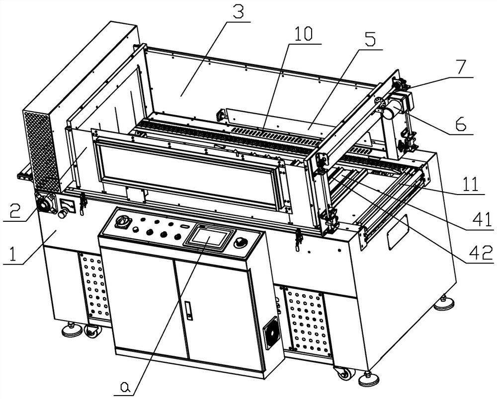
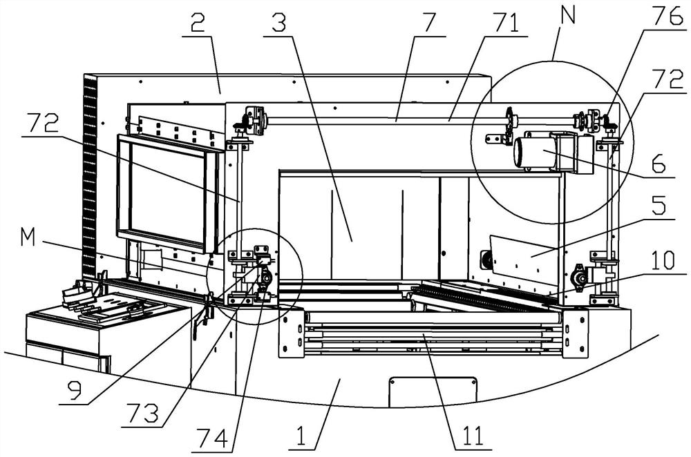
[0027] This embodiment includes a base 1 and an upper frame 2, the upper frame 2 is arranged on the base 1, the upper frame 2 and the base 1 enclose a heat shrinkable space 3, the base 1 is provided with a conveyor belt 11 for conveying materials, and the base 1 is provided with a heating The heating mechanism 12 and the air outlet mechanism 13 for blowing to the heating mechanism 12, the upper frame 2 forms the inlet and outlet of the material at both ends of the conveyor belt 11, and the left and right sides of the conveyor belt 11 are provided with side air outlets for side hot air to blow out 10. An air deflector 5 is arranged above the side air outlet 10, and the air deflector 5 is rotatably arranged on the...


PUM


Abstract

The invention discloses a shrinking machine. A heat shrinkage space is defined by an upper frame and a base of the shrinking machine, a conveying belt is arranged on the base, a heating mechanism and an air outlet mechanism are arranged in the base, the upper frame forms material inlets and outlets in the two ends of the conveying belt, side air outlets are formed in the left side and the right side of the conveying belt, and an air guide plate with the angle capable of being rotationally adjusted is arranged above the side air outlets. A first air baffle is arranged above the heating mechanism, a plurality of air outlets are formed in the first air baffle in the material conveying direction, a second air baffle is arranged below the first air baffle, and a plurality of air guide openings corresponding to the air outlets are formed in the second air baffle in the material conveying direction. The second air baffle is slidably arranged and is driven by a second driving mechanism to slide in the material conveying direction, and the overlapping size of the air guide openings and the air outlets is adjusted. A control module is used for automatically adjusting the air outlet angles on the two sides and the air outlet volume below, so that films of different specifications achieve a better heat shrinkage effect.

Description

technical field [0001] The invention relates to the field of product packaging, in particular to a shrinking machine. Background technique [0002] Heat shrink packaging machine is one of the more advanced packaging machinery in the market. The shrink film is used to wrap the product outside, and the shrink film is heated to make the product tightly wrapped, which fully displays the appearance of the product, improves the product's displayability, and increases the beauty and value. [0003] In the shrinking machine in the prior art, the air guiding mechanism and the heating mechanism are arranged under the conveying space, and the conveying space is conveyed by the conveyor belt to convey the product covered with the film, and the heat generated by the heating mechanism is blown upward through the air guiding mechanism to heat the film. Shrinkage; the general machine only blows upwards, and does not limit the direction of the wind. When dealing with products of different s...

Claims


Application Information

Patent Timeline
Patent Type & Authority Applications(China)
IPC IPC(8): B65B53/06B65B57/00
CPCB65B53/06B65B57/00
Inventor 厉勇郑迪
Owner ZHEJIANG DINGYE MACHINERY
Why Eureka
Try Eureka