Continuous storage device for furniture gap blocking rubber strips

A storage device and rubber strip technology, applied in the directions of packaging, transportation and packaging, packaging/bundling items, etc., can solve the problems of insecure packaging work, large size of rubber and plastic rings, poor packaging effect, etc., achieving a high degree of automation and saving Production cost and ease of handling

Inactive Publication Date: 2021-04-09
浙江笙龙家具有限公司
View PDF0 Cites 0 Cited by
  • Summary
  • Abstract
  • Description
  • Claims
  • Application Information

AI Technical Summary

Problems solved by technology

[0005] The purpose of the present invention is to address the deficiencies of the prior art, by setting the mold upper loading mechanism to cooperate with the winding mechanism, to realize the packing work of the rolled rubber and plastic ring, and then to facilitate its output and handling work one by one, thereby It solves the traditional packaging work of extruded rubber and plastic rings, and packs them with ropes or adhesive tapes. However, due to the large volume of rubber and plastic rings, the packing work is not firm, and the ropes are easy to break during transportation. Poor technical issues

Method used


Image

  • Continuous storage device for furniture gap blocking rubber strips
  • Continuous storage device for furniture gap blocking rubber strips
  • Continuous storage device for furniture gap blocking rubber strips

Examples


Embodiment 1

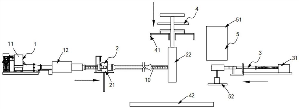
[0068] Such as figure 1 As shown, a furniture gap sealing rubber strip continuous storage device, including:

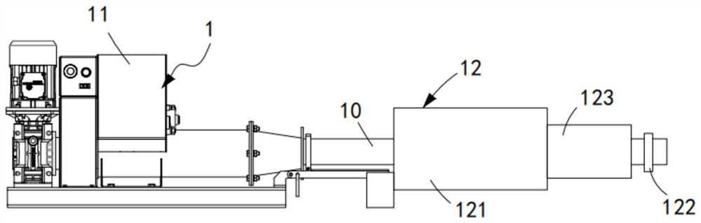
[0069] A transmission mechanism 1, the transmission mechanism 1 comprising an extruder 11 and a cooling assembly 12 arranged at the output end of the extruder 11;

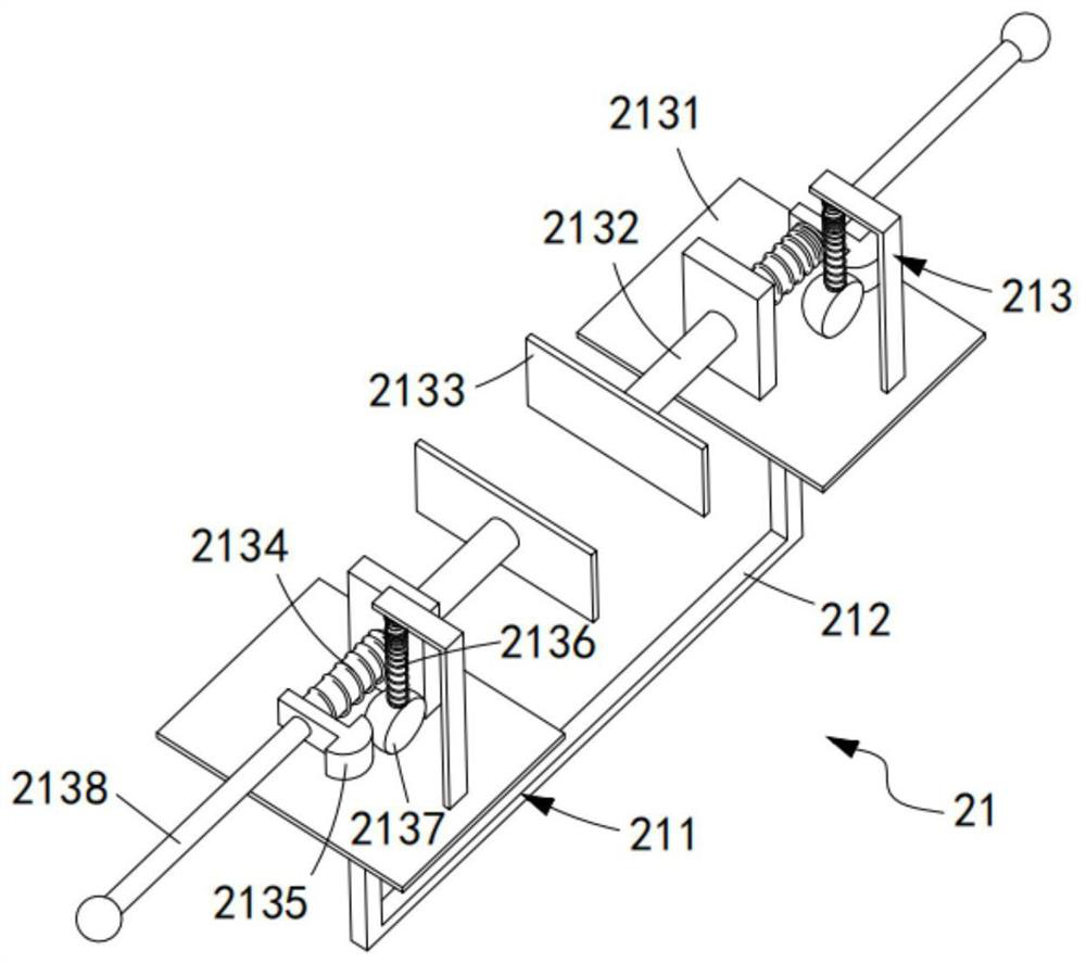
[0070] A traction mechanism 2, the traction mechanism 2 includes a clamping component 21 disposed at the output end of the cooling component 12 and a support component 22 disposed on one side of the clamping component 21 and matched with the clamping component 21;

[0071] The winding mechanism 3, the winding mechanism 3 includes a hoop assembly 31 arranged on one side of the support assembly 22 and a cutting assembly synchronously driven with the hoop assembly 31 and used for cutting the rubber strip 10 32. A clamping mold 33 is placed on the hoop assembly 31;

[0072] The output mechanism 4, the output mechanism 4 includes a push-down assembly 41 arranged directly above the support assembly 22 and a tr...

Embodiment 2

[0112] Such as Figure 13 to Figure 17 As shown, the components that are the same as or corresponding to those in the first embodiment are marked with the corresponding reference numerals in the first embodiment. For the sake of simplicity, only the differences from the first embodiment will be described below. The difference between this embodiment two and embodiment one is:

[0113] further, such as Figure 13 to Figure 15 As shown, the hoop assembly 31 includes:

[0114] A driving cylinder 311, the driving cylinder 311 is installed on the cylinder frame and its output end slides along the vertical direction and is provided with a telescopic unit c312;

[0115] A connecting frame b313, the connecting frame b313 is fixedly connected to the other end of the telescopic unit c312;

[0116] The connecting plate a314, the connecting plate a314 is slid and arranged on the cylinder frame along the vertical direction through two sets of telescopic units d315;

[0117] Tightening ...


PUM


Abstract

The invention relates to a continuous storage device for furniture gap blocking rubber strips. The continuous storage device comprises a conveying mechanism, a traction mechanism, a winding mechanism, an output mechanism and a mold loading mechanism, wherein the conveying mechanism comprises an extruder and a cooling assembly; the traction mechanism comprises a clamping assembly and a supporting assembly; the winding mechanism comprises a hoop assembly arranged on one side of the supporting assembly and a cutting assembly which is in synchronous transmission with the hoop assembly and is used for slitting the rubber strips, and a clamping mold is placed on the hoop assembly; the output mechanism comprises a push-down assembly and a conveying belt; and the mold loading mechanism comprises a mold storage assembly arranged above the hoop assembly and a conveying assembly used for driving the mold storage assembly to automatically enter the hoop assembly. According to the continuous storage device, the technical problems that in the traditional packaging work of extruded and formed rubber and plastic rings, the rubber and plastic rings are packaged by adopting a rope or adhesive tape bonding mode, but due to the fact that the size of the rubber and plastic rings is large, the packaging work is not firm, the rope is prone to breakage in the carrying process, and the packaging effect is poor are solved.

Description

technical field [0001] The invention relates to the technical field of furniture gap sealing rubber strips, in particular to a continuous storage device for furniture gap sealing rubber strips. Background technique [0002] As an important part of people's daily necessities, existing furniture occupies an increasingly important position. After purchasing furniture, place it according to its use space. When the furniture is placed against the wall, there will be a gap between the furniture and the wall. It affects the overall effect of home decoration and is not beautiful enough. The second is that small daily necessities tend to slip along the gap and fall into the gap between the furniture and the wall. It is difficult to take it out. It needs to move the furniture to take it out. It is easy to cause damage and deformation of the furniture, so a beautiful, fixed and firm barrier strip is required to seal the gap between the furniture and the wall. [0003] The patent docum...

Claims


Application Information

Patent Timeline
Patent Type & Authority Applications(China)
IPC IPC(8): B65B63/04B65B13/18B65B27/06B29C48/28B29C48/25B29C48/885
CPCB65B13/185B65B27/06B65B63/04B29C48/0022B29C48/25B29C48/28B29C48/885
Inventor 张贵生
Owner 浙江笙龙家具有限公司
Why Eureka
Try Eureka