
Wide-angle lens and imaging equipment

A technology of wide-angle lens and imaging surface, which is applied in the field of imaging lens, can solve the problems of not being able to satisfy photographers, poor compression of central and peripheral field of view, and poor stability of the use environment, etc., and achieve reasonable focal power and surface shape settings , high-order aberration correction, and high-resolution effects

Active Publication Date: 2021-04-09
JIANGXI LIANCHUANG ELECTRONICS CO LTD
View PDF4 Cites 4 Cited by
  • Summary
  • Abstract
  • Description
  • Claims
  • Application Information

AI Technical Summary

Problems solved by technology

[0003] High-definition wide-angle action cameras have entered the market for some time, and the market has transitioned from the initial design novelty to the cost-effective trade-off stage, and with the continuous development of chip technology, the price of high-pixel and large CRA (Chief Ray Angle, chief ray angle) chips continues to decrease , has gradually become the main force in the market, but due to the small field of view of the general lens, the compression of the center and the edge of the field is relatively poor, and the stability of the use environment is poor, it cannot meet the needs of photographers for high-pixel sports lenses.

Method used


Image

  • Wide-angle lens and imaging equipment
  • Wide-angle lens and imaging equipment
  • Wide-angle lens and imaging equipment

Examples


no. 1 example

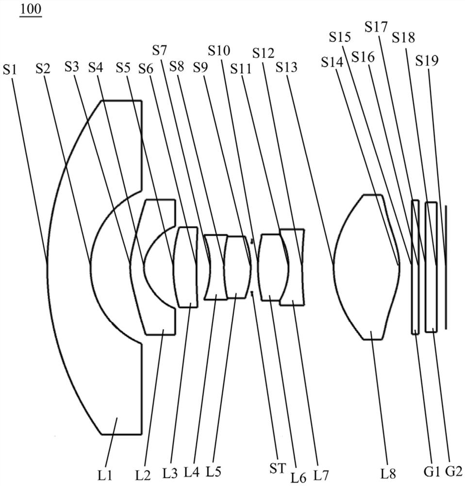
[0085] see figure 1 , which is a schematic structural view of the wide-angle lens 100 provided in the first embodiment of the present invention. The wide-angle lens 100 includes in sequence from the object side to the imaging surface along the optical axis: a first lens L1, a second lens L2, a third lens L3, a fourth lens Lens L4, fifth lens L5, sixth lens L6, seventh lens L7, eighth lens L8, filter G1, and cover glass G2.

[0086] The first lens L1 has negative refractive power, the object side S1 of the first lens is a convex surface, the image side S2 of the first lens is a concave surface, and the first lens L1 is a glass spherical lens; the first lens L1 can be made of a material with higher hardness , to increase the anti-drop performance of the overall lens.

[0087] The second lens L2 has negative refractive power, the object side S3 of the second lens is convex, the image side S4 of the second lens is concave, and the second lens L2 is a glass spherical lens.

[008...

no. 2 example

[0107] see Figure 5 , is a schematic structural diagram of the wide-angle lens 200 provided by the second embodiment of the present invention. The structure of the wide-angle lens 200 in the present embodiment is roughly the same as that of the wide-angle lens 100 in the first embodiment, except that the image side of the seventh lens of the wide-angle lens 200 in the present embodiment is a convex surface, and the parameters of each lens are different , and the lens-related parameters of each lens are shown in Table 3.

[0108] table 3

[0109]

[0110]

[0111] Table 4 shows the parameters related to the aspheric surface of each lens in the wide-angle lens 200 provided in this embodiment.

[0112] Table 4

[0113] face number K B C D E F S3 1.31E+02 -5.34E-03 -1.19E-03 1.65E-04 1.38E-05 -4.69E-07 S4 3.39E-01 -2.48E-02 -3.23E-03 -7.03E-04 1.78E-05 6.15E-07 S13 -9.19E-01 -1.88E-03 -3.61E-04 5.81E-05 5.76E-06 -3.78E-07 ...

no. 3 example

[0128] see Figure 9 , The third embodiment of the present invention provides an imaging device 300, the imaging device 300 includes an imaging element 310 and the wide-angle lens (such as the wide-angle lens 100) in any of the above-mentioned embodiments. The imaging element 310 may be a CMOS (Complementary Metal Oxide Semiconductor, Complementary Metal Oxide Semiconductor) image sensor, and may also be a CCD (Charge Coupled Device, Charge Coupled Device) image sensor.

[0129] The imaging device 300 may be a sports camera, a drone, or any other electronic device loaded with the wide-angle lens 100 .

[0130] The imaging device 300 provided in the embodiment of the present application includes the wide-angle lens in any of the above-mentioned embodiments. Since the wide-angle lens has the advantages of large wide-angle, high pixels, and low image plane drift in high and low temperature environments, the imaging device 300 with this wide-angle lens also has a large wide-angle,...


PUM


Abstract

The invention discloses a wide-angle lens and imaging equipment, and the wide-angle lens sequentially comprises from an object side to an imaging surface along an optical axis: a first lens with negative focal power, wherein the object side surface of the first lens is a convex surface, and the image side surface of the first lens is a concave surface; a second lens with negative focal power, wherein the object side surface of the second lens is a convex surface, and the image side surface of the second lens is a concave surface; a third lens with positive focal power, wherein the object side surface of the third lens is a convex surface, and the image side surface of the third lens is a concave surface; a fourth lens with negative focal power, wherein the object side surface and the image side surface of the fourth lens are concave surfaces; a fifth lens with positive focal power, wherein the object side surface and the image side surface of the fifth lens are convex surfaces; a diaphragm; a sixth lens with positive focal power, wherein the object side surface and the image side surface of the sixth lens are convex surfaces; a seventh lens with negative focal power, wherein the object side surface of the seventh lens is a concave surface, and the image side surface of the seventh lens is a convex surface or a concave surface; and an eighth lens with positive focal power, wherein the object side surface and the image side surface of the eighth lens are convex surfaces. The wide-angle lens has the advantages of being small in size, high in imaging quality, small in high-temperature and low-temperature environment image surface drift and the like.

Description

technical field [0001] The invention relates to the technical field of imaging lenses, in particular to a wide-angle lens and imaging equipment. Background technique [0002] The development of mobile Internet has made photos and videos a trend of sharing on the Internet to record every bit of life, which gave birth to action cameras. Since sports cameras are mostly used in environments with severe vibration, high pressure and extreme temperature, the requirements for the matching camera lenses are extremely high. On the one hand, it is necessary to solve the problem of taking pictures at any place and in any direction, and it requires high-definition imaging. The effect also requires a large field of view to meet the image shooting in a large field of view. [0003] High-definition wide-angle action cameras have entered the market for a while, and the market has transitioned from the initial design novelty to the cost-effective trade-off stage. With the continuous developm...

Claims


Application Information

Patent Timeline
Patent Type & Authority Applications(China)
IPC IPC(8): G02B13/00G02B13/06G02B13/18G02B1/00
CPCG02B13/0045G02B13/006G02B13/06G02B13/18G02B1/00
Inventor 高博李伟娜韩建鲍海江兰喜艳曾吉勇
Owner JIANGXI LIANCHUANG ELECTRONICS CO LTD
Learn More