Static contact for switch cabinet, and switch cabinet

A switchgear and static contact technology, applied in electrical switches, contacts, contact meshing, etc., can solve the problem of high manufacturing cost of switchgear, and achieve the effects of improving heat dissipation efficiency, reducing costs, and improving current capacity

Pending Publication Date: 2021-04-09
TIANJIN PINGGAO INTELLIGENT ELECTRIC +2
View PDF14 Cites 1 Cited by
  • Summary
  • Abstract
  • Description
  • Claims
  • Application Information

AI Technical Summary

Problems solved by technology

[0004] The purpose of the present invention is to provide a static contact for switchgear to solve the technical problem that the switchgear in the prior art dissipates heat through the heat dissipation fan, resulting in high manufacturing cost of the switchgear; the purpose of the present invention is also to provide a switchgear

Method used


Image

  • Static contact for switch cabinet, and switch cabinet
  • Static contact for switch cabinet, and switch cabinet
  • Static contact for switch cabinet, and switch cabinet

Examples


Embodiment 1

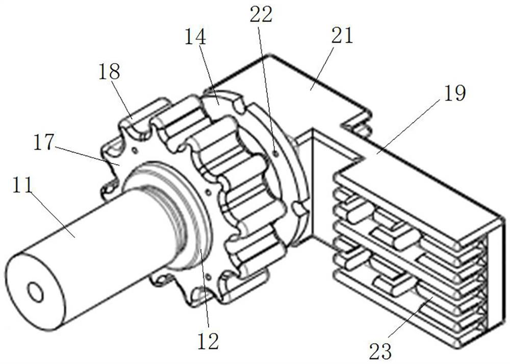
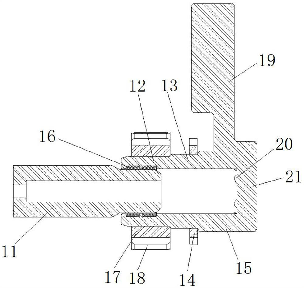
[0056] Such as figure 1 with figure 2 As shown, the static contact for switchgear includes a contact body, and the contact body includes a mating section 12, a small-diameter section 13 of the contact, a large-diameter section 15 of the contact, and a bus connection section 19, the mating section 12, the small-diameter section of the contact 13. The large-diameter section 15 of the contact and the connecting section 19 of the busbar are integrally formed, which makes the processing of the contact body convenient and stable in performance. Wherein, the small-diameter section 13 of the contact and the large-diameter section 15 of the contact jointly constitute a fixed part.

[0057] In this embodiment, the mating section 12, the small-diameter section 13 of the contact, and the large-diameter section 15 of the contact are connected in sequence, and all three are cylindrical structures; the mating section 12 is inserted into the contact arm 11 on the circuit breaker, mated The...

Embodiment 2

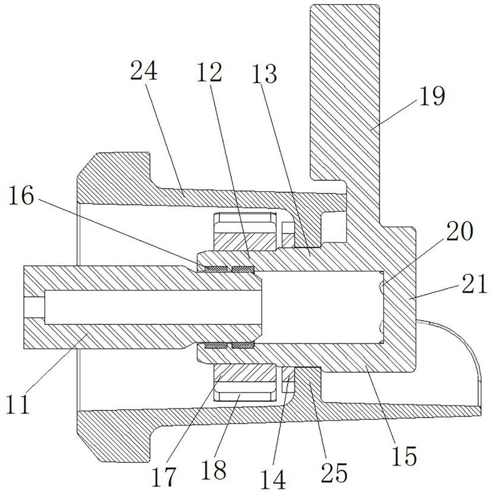
[0069] The difference between this embodiment and the first embodiment is that in embodiment 1, the static contact includes a mating section 12, a small-diameter contact section 13 and a large-diameter section 15 of the contact, and a fixing nut 14 is threaded on the small-diameter section 13 of the contact. The static contact is fixed in the contact box 24 through the fixing nut 14, and the mating section 12 is inserted into the contact arm. In this embodiment, the static contact only includes a mating section, a fixing hole is provided at the bottom of the mating section, and an insert is embedded in the contact box, and the static contact is fixed on the insert by screws to realize fixing on the contact box. inside the header box.

Embodiment 3

[0071] The difference between this embodiment and the first embodiment is that in embodiment 1, the contact small-diameter section 13 is located between the contact large-diameter section 15 and the mating section 12, and the heat dissipation device is detachably fixed on the mating section 12. The section 12, the small-diameter section 13 of the contact, the large-diameter section 15 of the contact and the busbar connection section 19 are integrally formed, and the static contact is loaded from the right side of the partition 25 as a whole when assembled. In this embodiment, the cooling device is integrally formed on the mating section, and the large-diameter section of the contact is detachably connected to the small-diameter section of the contact. When the static contact is assembled, the mating section and the small-diameter section of the contact are installed from the left side of the partition. The large-diameter section of the contact is loaded from the right side of t...


PUM


Abstract

The invention relates to a static contact for a switch cabinet, and the switch cabinet. The static contact for the switch cabinet comprises: a contact body used for being fixed in a contact box of the switch cabinet, wherein the contact body comprises an insertion section, the insertion section is of a cylindrical structure and is used for allowing a contact arm on a circuit breaker to be inserted, and an annular contact finger installation groove is formed in the inner wall face of the insertion section; an annular contact finger mounted in the contact finger mounting groove and used for being in conductive contact with a contact arm on the circuit breaker; and an insertion section cooling fin arranged at the position, corresponding to the annular contact finger, of the outer peripheral surface of the insertion section. The static contact and the contact arm are in direct plug-in fit, so that the centering of the contact arm and the static contact can be better realized, the contact arm and the static contact are better in contact, and the through-current capability is ensured; and the insertion section radiating fins are arranged at the positions, corresponding to the annular contact fingers, of the outer peripheral surface of the insertion section, so that natural dissipation of heat is realized, the cost is reduced, the partial discharge sound in the switch cabinet cannot be masked, and timely discovery of insulation faults is facilitated.

Description

technical field [0001] The invention relates to a static contact for a switch cabinet and a switch cabinet. Background technique [0002] As the structure of the distribution network becomes more and more complex, the load on the system is increasing, and the temperature rise of the contact position of the static contact in the contact box of the high-current switchgear and the contact position of the contact arm on the circuit breaker also needs to meet the requirements. [0003] At present, a high-power cooling fan is generally installed on the switchgear to meet the temperature rise requirements. However, once the cooling fan fails and is not detected in time, it will cause serious temperature rise failure, and then cause insulation failure; moreover, the high-power cooling fan will generate large noise during operation, which will cover up the partial discharge in the switch cabinet The sound is not conducive to the timely detection of insulation faults. In addition, t...

Claims


Application Information

Patent Timeline
Patent Type & Authority Applications(China)
IPC IPC(8): H01H1/38H01H1/50H01H1/58H01H1/62H01H1/64H02B1/30
CPCH01H1/38H01H1/50H01H1/62H01H1/64H01H1/58H02B1/30
Inventor 李红雷汪宁陈利民张敬涛张罗锐陈金英丛艳伟曹博宇尹婷焦淑敏张晓丁谢培哲王茜
Owner TIANJIN PINGGAO INTELLIGENT ELECTRIC
Why Eureka
Try Eureka