Activated carbon adsorption device for organic waste gas purification
A technology of activated carbon adsorption and organic waste gas, which is applied in gas treatment, chemical instruments and methods, membrane technology, etc., can solve the problems of poor purification ability, inability to activate carbon adsorption, labor-intensive and other problems, and achieve the effect of prolonging the use time.
- Summary
- Abstract
- Description
- Claims
- Application Information
AI Technical Summary
Problems solved by technology
Method used
Image

Examples
Embodiment Construction
[0022] The following will clearly and completely describe the technical solutions in the embodiments of the present invention with reference to the accompanying drawings in the embodiments of the present invention. Obviously, the described embodiments are only some, not all, embodiments of the present invention. Based on the embodiments of the present invention, all other embodiments obtained by persons of ordinary skill in the art without making creative efforts belong to the protection scope of the present invention.
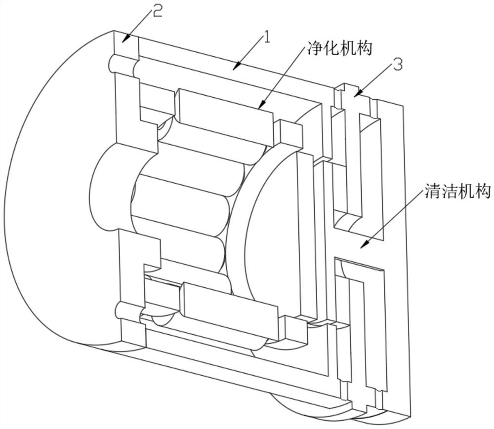
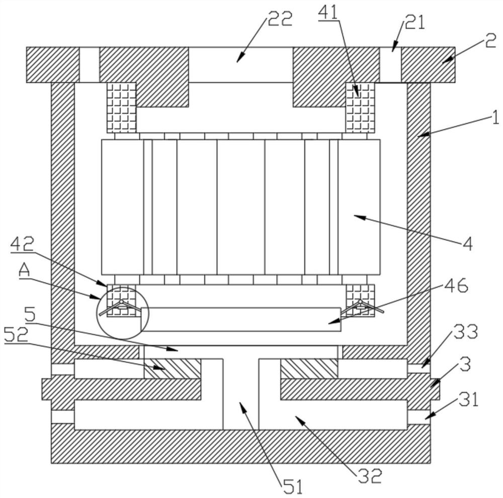
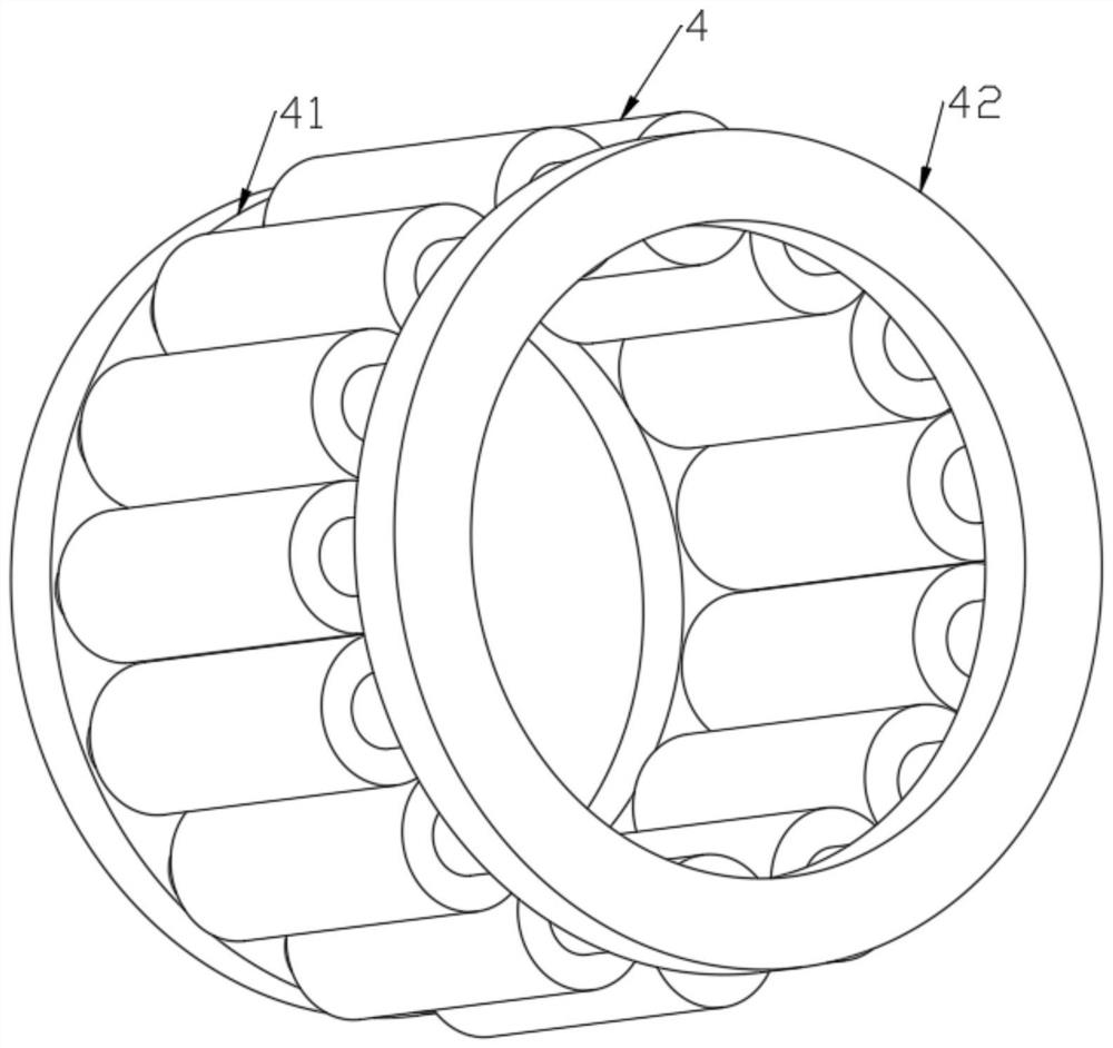
[0023] see Figure 1-4 , the present invention provides a technical solution: an activated carbon adsorption device for organic waste gas purification, comprising a shell 1, characterized in that: one end of the shell 1 is welded with a shell cover 2, one end of the shell 1 is welded with a shell seat 3, the shell 1 is snapped with a purification mechanism, the interior of the purification mechanism is provided with a purification column 4, the interior of the...
PUM
 Abstract
Description
Claims
Application Information