Airbag engaged type windproof damping door stopper
A kind of air bag and fitting technology, which is applied in the direction of building fastening devices, wing leaf fastening devices, buildings, etc., can solve the problems of door suction impact, easy damage, automatic door closing, etc., to prolong life, reduce friction, The effect of small effort
- Summary
- Abstract
- Description
- Claims
- Application Information
AI Technical Summary
Problems solved by technology
Method used
Image

Examples
Embodiment Construction
[0032] The technical solutions in the embodiments of the present application will be clearly and completely described below in conjunction with the drawings in the embodiments of the present application. Apparently, the described embodiments are only some of the embodiments of the present application, not all of them. Based on the embodiments in this application, all other embodiments obtained by persons of ordinary skill in the art without making creative efforts belong to the scope of protection of this application. The accompanying drawings in the embodiments of the present application: the different types of section lines in the drawings are not marked according to the national standard, and the material of the components is not required, but the cross-sectional views of the components in the drawings are distinguished.
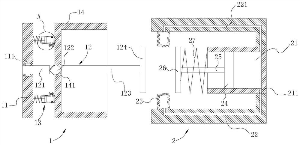
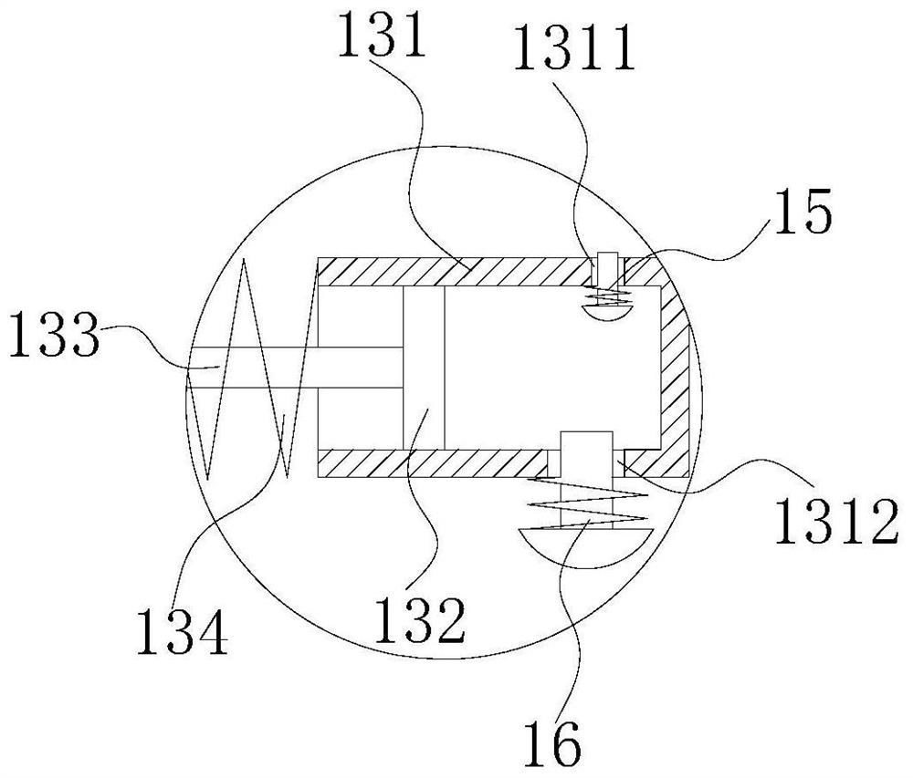
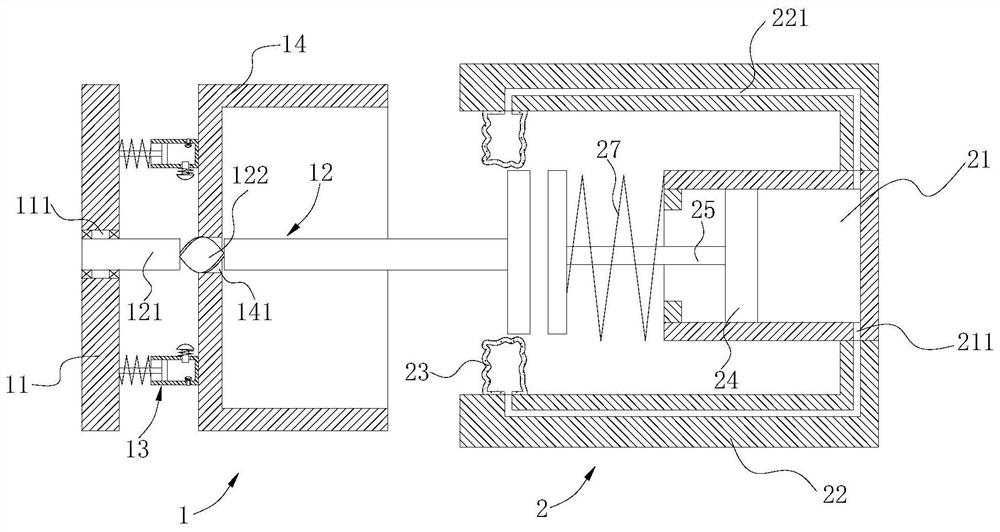
[0033] see Figure 1-7 The airbag-engaging windproof and shock-absorbing door stop shown is an airbag-engaging windproof and shock-absorbing door stopper...
PUM
 Abstract
Description
Claims
Application Information
PatSnap Eureka turns technology decisions into work you can execute. Powered by our Innovation Knowledge Graph, it runs expert workflows across engineering, life sciences, materials and intellectual property. Get your review-ready output in minutes.


