Linear reciprocating piston type compressor and using method thereof

A linear reciprocating, piston-type technology, used in piston pumps, liquid variable-capacity machinery, mechanical equipment, etc., can solve the problems of increased wear and increased power consumption of compressors, and achieve increased wear, reduced wear, and reduced impact wear. Effect

Inactive Publication Date: 2021-04-13
大丰全力机械有限公司
View PDF6 Cites 0 Cited by
  • Summary
  • Abstract
  • Description
  • Claims
  • Application Information

AI Technical Summary

Problems solved by technology

[0002] At present, most compressors use a motor to drive the crankshaft of the compressor to rotate, and then the crankshaft drives the connecting rod to push the piston of the compressor, or the crankshaft drives the swinging piston of the connecting rod and the piston to compress gas or liquid to do work. Due to the connection between the crankshaft and the connecting rod of the compressor of the structure, the crankshaft is directly inserted into the connecting hole of the connecting rod, and the crankshaft drives the connecting rod to swing and reciprocate. Increase the power consumption of the compressor and increase the wear and tear

Method used


Image

  • Linear reciprocating piston type compressor and using method thereof
  • Linear reciprocating piston type compressor and using method thereof
  • Linear reciprocating piston type compressor and using method thereof

Examples


Embodiment

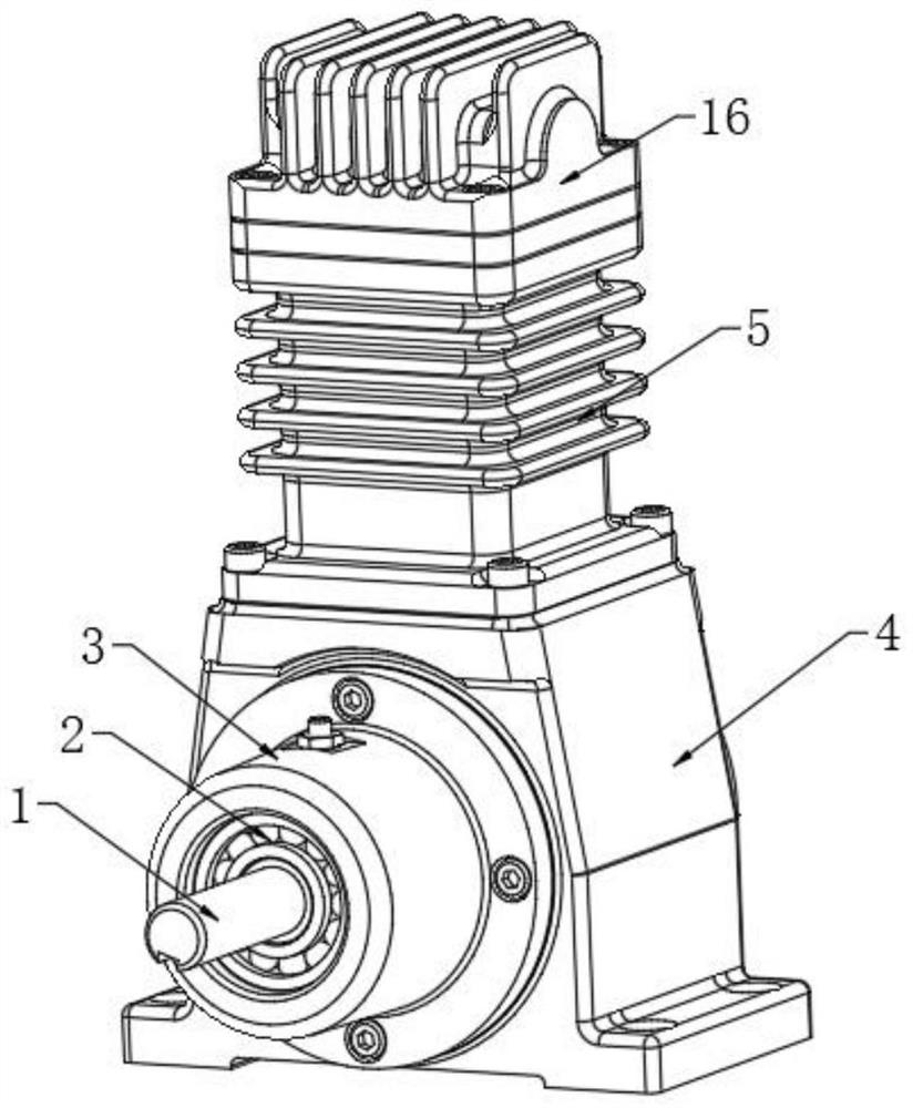
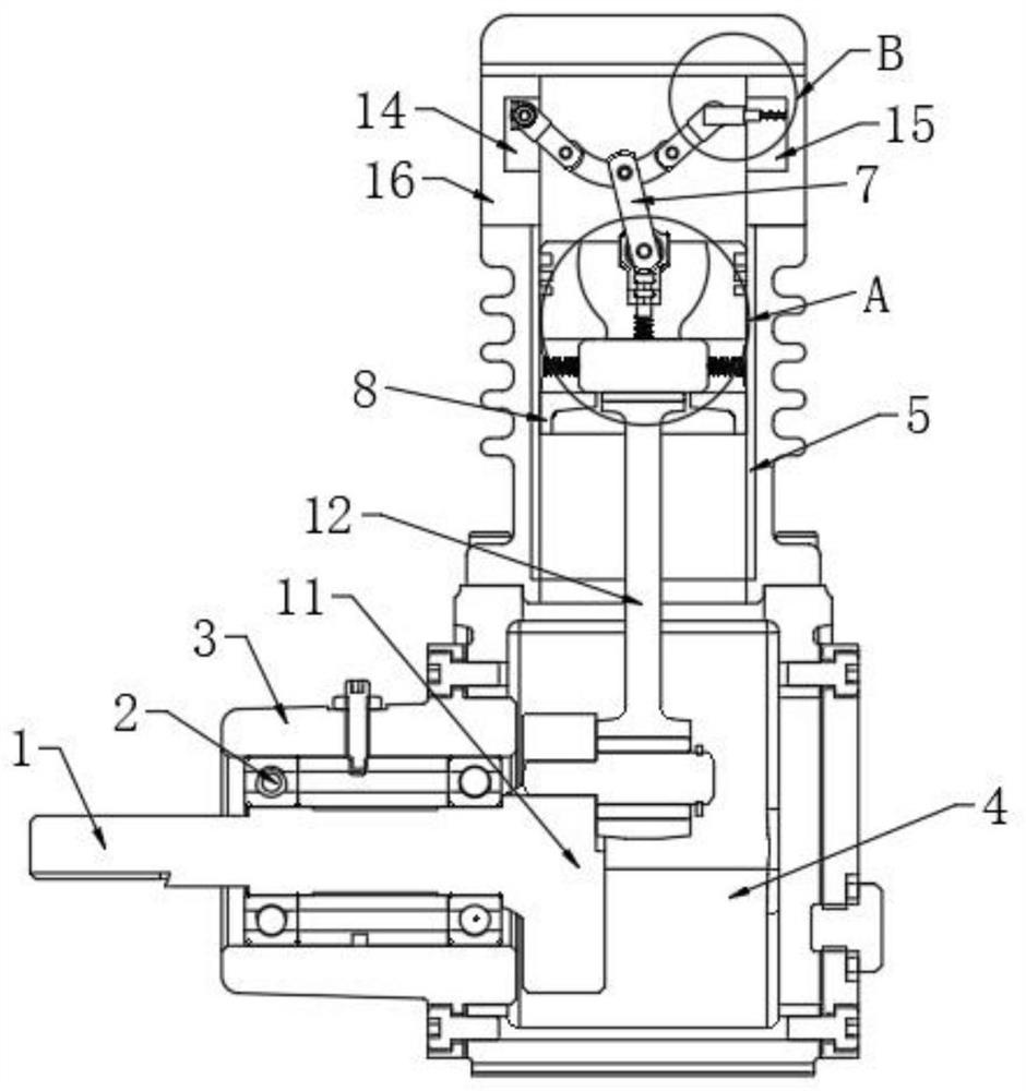
[0037] see Figure 1-6 , a linear reciprocating piston compressor, consisting of a first cylinder block 4, a piston 8, a rotating shaft 1, a crankshaft 11, a connecting rod 12, a first movable mechanism 6 and a second movable mechanism 7.

[0038]Wherein, the left side wall of the first cylinder block 4 is fixedly connected with a fixed column 3, and the fixed column 3 plays a role of supporting the rotating shaft 1, and the upper end of the first cylinder block 4 is fixedly connected with a second cylinder block 5, The inner wall of the second cylinder block 5 is smeared with lubricating oil, which not only reduces the friction between the piston 8 and the second cylinder block 5, but also reduces the noise. The upper end of the second cylinder block 5 is fixedly connected with a hollow casing 16. The inner cavity of the hollow casing 16 is used as the moving space of the second moving mechanism 7, and the inner cavities between the first cylinder block 4, the second cylinder...


PUM


Abstract

The invention discloses a linear reciprocating piston type compressor. The linear reciprocating piston type compressor comprises a first air cylinder body, a fixed column, a second air cylinder body, a hollow housing, a rotating shaft, a crankshaft, a piston, a linkage rod, a first movable mechanism and a second movable mechanism; the piston is slidably connected to the inner wall of the second air cylinder body, the piston comprises a shell, a third limiting groove is formed in the upper surface of the shell, a second limiting groove is formed in the bottom of the third limiting groove, and a first limiting groove is formed in the bottom of the second limiting groove; the connecting rod is fixedly connected to the right end of the crankshaft, a connecting disc is welded to the upper end of the connecting rod, third springs are welded to the left side wall and the right side wall of the connecting disc, and the other ends of the third springs are welded to the inner wall of the second limiting groove; the first movable mechanism is located in the third limiting groove and fixedly connected to the upper end of the connecting disc; the second movable mechanism is located in an inner cavity of the hollow housing and movably connected to the upper end of the first movable mechanism through a first movable column. The lateral friction resistance of the compressor can be reduced, abrasion is reduced, and the working efficiency of the compressor is improved.

Description

technical field [0001] The present invention relates to the technical field of linear reciprocating piston compressors, and more specifically relates to a linear reciprocating piston compressor and its usage method. Background technique [0002] At present, most compressors use a motor to drive the crankshaft of the compressor to rotate, and then the crankshaft drives the connecting rod to push the piston of the compressor, or the crankshaft drives the swinging piston of the connecting rod and the piston to compress gas or liquid to do work. Due to the connection between the crankshaft and the connecting rod of the compressor, the crankshaft is directly inserted into the connecting hole of the connecting rod, and the crankshaft drives the connecting rod to swing and reciprocate. Increase the power consumption of the compressor and increase the wear and tear. Contents of the invention [0003] The present invention provides a linear reciprocating piston compressor and its ...

Claims


Application Information

Patent Timeline
Patent Type & Authority Applications(China)
IPC IPC(8): F04B37/12F04B35/04F04B39/00F04B39/12
CPCF04B37/12F04B39/00F04B35/04F04B39/0044F04B39/122F04B39/0005
Inventor 茅永国
Owner 大丰全力机械有限公司
Why Eureka
Try Eureka