A method for creating visual area of ​​combined instrument display plane based on catia software

A combined instrument and plane technology, which is applied in the field of creating the visual area of ​​the combined instrument display plane, can solve the problems of complex methods and low precision, and achieve the effects of simple operation, high design precision and reliable modeling results

Active Publication Date: 2022-05-17
DONGFENG AUTOMOBILE COMPANY
View PDF8 Cites 0 Cited by
  • Summary
  • Abstract
  • Description
  • Claims
  • Application Information

AI Technical Summary

Problems solved by technology

[0005] The purpose of the present invention is to overcome the problems of complicated methods and low precision in the prior art, and provide an easy-to-understand, high-precision method for creating a visual region of a combined instrument display plane based on CATIA software

Method used


Image

  • A method for creating visual area of ​​combined instrument display plane based on catia software
  • A method for creating visual area of ​​combined instrument display plane based on catia software
  • A method for creating visual area of ​​combined instrument display plane based on catia software

Examples


Embodiment 1

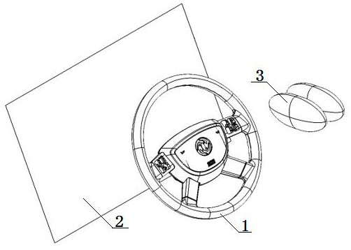
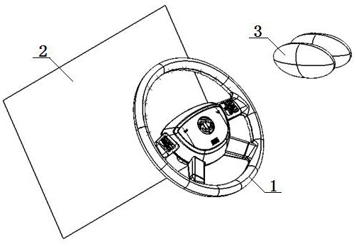
[0060] A method for creating a visual area of ​​a display plane of a combination instrument based on CATIA software, comprising the following steps: the first step: creating a simulation interface, combining a steering wheel 1 with a known relative positional relationship, a display plane 2 of a combination instrument and a pair of 95 percentiles The bit-eye ellipse 3 is created in the 3D display interface, and the positions of the above three are adjusted to meet their relative positional relationship;

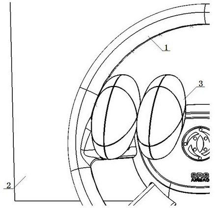
[0061] Step 2: Create the upper boundary of the visible area, make evenly distributed points on the inner tangent line of the upper rim of the horn cover of the steering wheel 1, and make visible tangent lines at the evenly distributed points on the inner tangent line of the rim, and obtain the left and right eye ellipses 3 On the upper boundary of the visible area on the display plane 2 of the instrument combination, according to the upper boundary of the visible area on the ...

Embodiment 2

[0065] Embodiment 2 is basically the same as Embodiment 1, and its difference is:

[0066] The second step: create the upper boundary of the visible area, make a plurality of evenly distributed points on the intangent line of the upper rim of the horn cover of the steering wheel 1, adjust the 3D display interface so that the intangent line of the rim and the left eye ellipse 3 The outer surface is tangent at the first uniform point on the left, move the compass to the first uniform point on the left, keep the viewing angle unchanged, and define the direction of the main plane of the compass to be parallel to the computer display screen, making and computer display The surface is parallel to the screen, move the surface to the vicinity of the combination instrument display plane 2, project the first evenly distributed point to the created plane as the projection point, connect the first uniformly distributed point and the projected point to make the first uniformly distributed p...

Embodiment 3

[0075] Embodiment 3 is basically the same as Embodiment 2, and its difference is:

[0076] The second step: in creating the upper boundary of the visible area, make at least 8 evenly distributed points on the intangent line of the upper rim of the horn cover of the steering wheel 1 .

[0077] The third step: in creating the lower boundary of the viewing area, make at least 6 uniformly distributed points on the outer tangent line of the upper part of the horn cover trim.


PUM


Abstract

A CATIA software-based method for creating a visual area of ​​a combined instrument display plane, comprising the following steps: the first step: creating a simulation interface; the second step: creating the upper boundary of the visual area; the third step: creating the lower boundary of the visual area Boundary; and the fourth step: obtain the visual area, combine the upper boundary of the total field of view of the left and right eye ellipses obtained in the second step with the lower boundary of the total field of view of the left and right eye ellipses obtained in the third step to obtain a possible viewing area. This design not only standardizes the modeling process and makes the modeling process clear, but also is simple to operate, easy to learn, and effectively improves the modeling efficiency.

Description

technical field [0001] The invention relates to a method for creating a visual area of ​​a display plane of a combined instrument based on CATIA software, which is particularly suitable for simplifying design steps and improving design precision. Background technique [0002] The combination instrument of the car displays various statuses and information of the vehicle, such as vehicle speed, engine speed, engine water temperature, oil level, handbrake status, whether the seat belt is fastened, engine failure, etc. The layout of the combined instrument is the instrument panel, and the visibility of the combined instrument is the basis for the layout of the combined instrument. [0003] The visible area of ​​the combination instrument refers to the area on the display plane of the combination instrument that can be seen by the eye point contained in the eye ellipse through the area between the upper part of the steering wheel horn cover and the steering wheel rim. [0004] T...

Claims


Application Information

Patent Timeline
Patent Type & Authority Patents(China)
IPC IPC(8): G06F8/38G06F8/34B60K35/00
CPCG06F8/38G06F8/34B60K35/00Y02T90/00
Inventor 万长林焦洪波李祎林徐远吴朝杨兴明刘鹏高标
Owner DONGFENG AUTOMOBILE COMPANY
Why Eureka
Try Eureka