
Welding device convenient to use and using method thereof

A welding device and a convenient technology, applied in auxiliary devices, separation methods, welding equipment and other directions, can solve the problems of inconvenient fixing and clamping of pipe fittings, and the use scene affects welding operations, etc., to facilitate welding operations, facilitate welding accuracy, and expand the scope of use. Effect

Inactive Publication Date: 2021-04-16
刘少波
View PDF1 Cites 2 Cited by
  • Summary
  • Abstract
  • Description
  • Claims
  • Application Information

AI Technical Summary

Problems solved by technology

The pipe fitting welding device in the above patent has the following disadvantages: it is inconvenient to fix and clamp pipe fittings of different sizes during welding, and the use scene is limited to affect the welding operation

Method used


Image

  • Welding device convenient to use and using method thereof
  • Welding device convenient to use and using method thereof
  • Welding device convenient to use and using method thereof

Examples


Embodiment 1

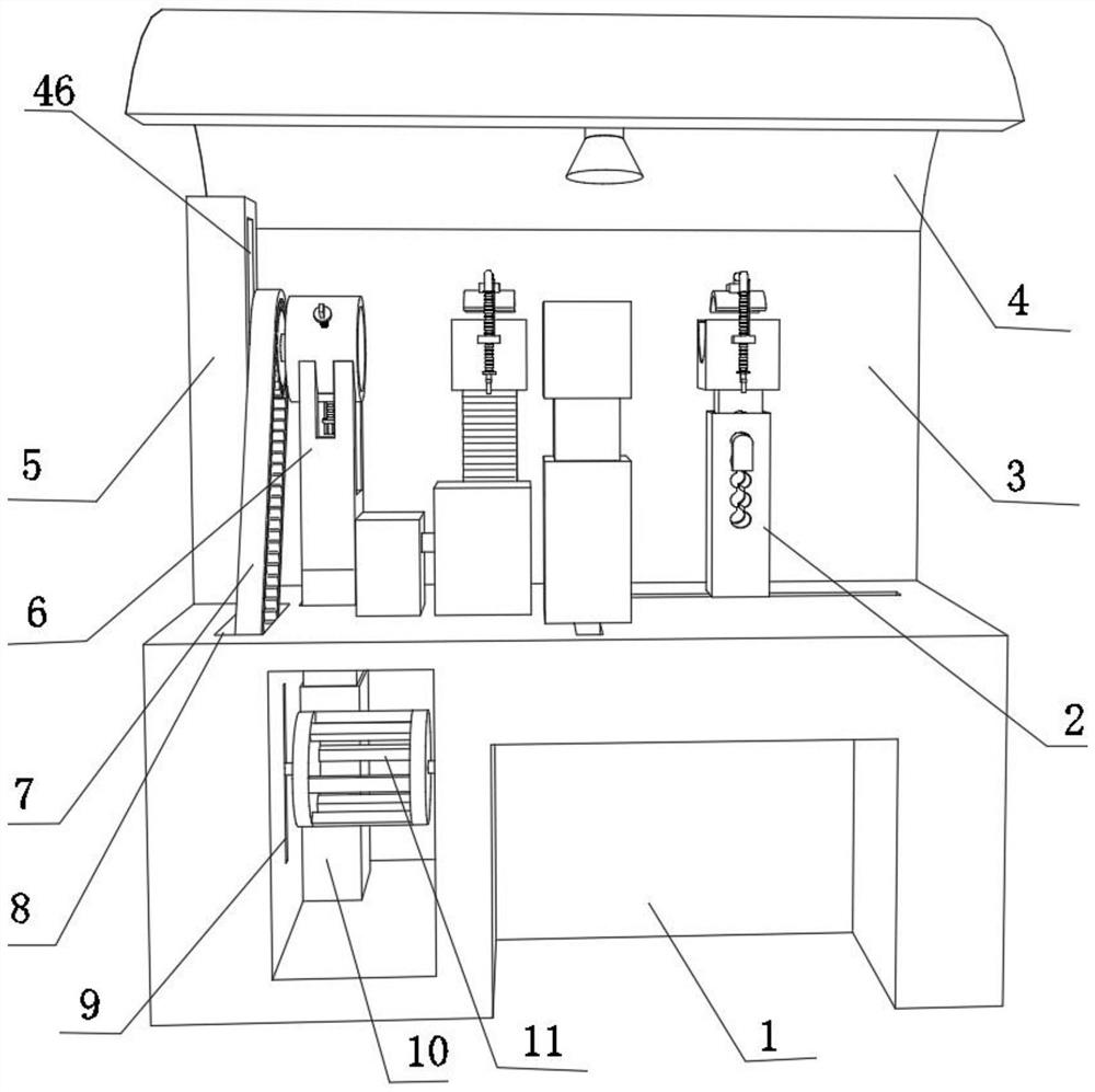
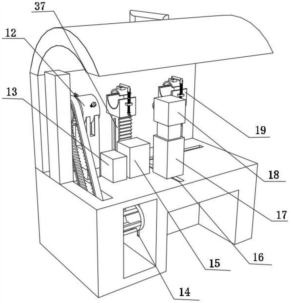
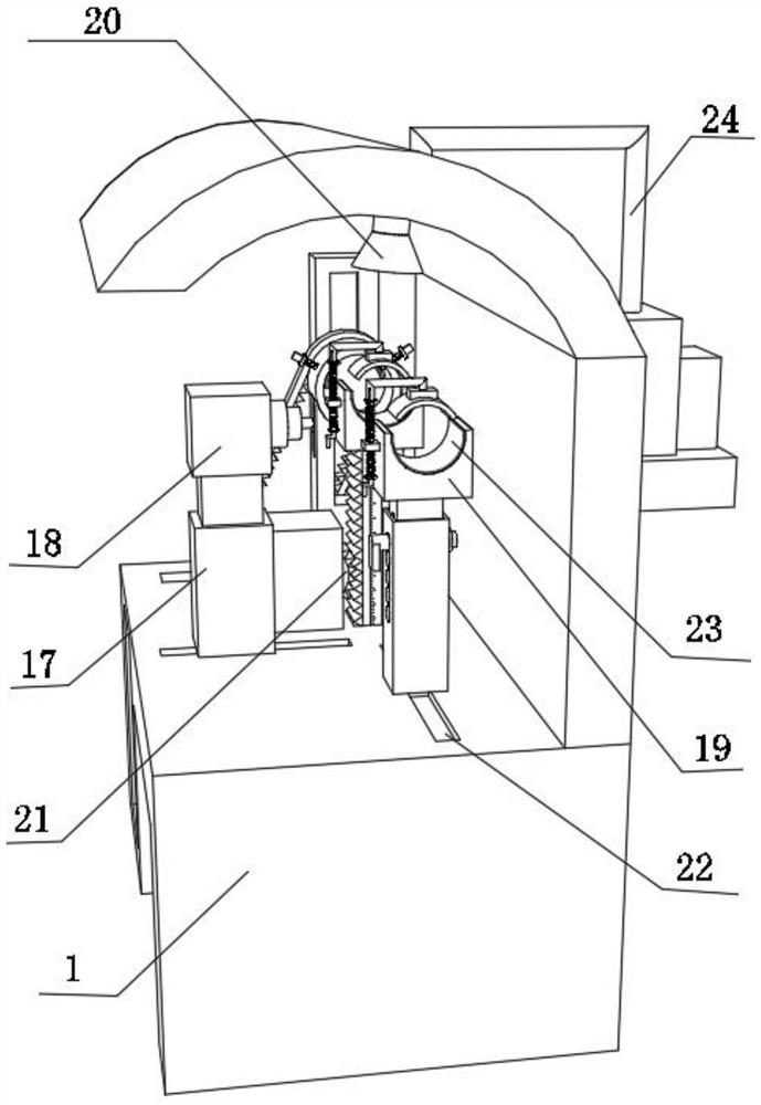
[0042] An easy-to-use welding device such as Figure 1-3 , Figure 5 , Figure 6 and Figure 8 As shown, including the body 1, the top outer wall of the body 1 is provided with a groove 29, and the inner wall on the opposite side of the groove 29 is fixed with a block 28 by bolts, and the inner walls of the two blocks 28 pass through the third chute respectively. 39 is slidably connected with the same elevating rod 37, and one side outer wall of the two third chute 39 is opened on the two side outer walls of elevating rod 37 respectively; The first lifting column 2 is slidably connected with the slider. The first lifting column 2 is a hollow structure. The outer walls of both sides of the first lifting column 2 are provided with first adjustment holes 33. The inner wall of the first lifting column 2 is inserted with a second Two lifting columns 30, and the top outer wall of the second lifting column 30 and the top outer wall of the lifting rod 37 are all fixed with a placem...

Embodiment 2

[0049] A method for using the easy-to-use welding device described in Embodiment 1, such as figure 1 shown, including the following steps:

[0050] S1: Adjust the height of the first lifting column 2 and the second lifting column 30, adjust the height of the lifting rod 37, so that the horizontal positions of the two placing seats 19 are equal;

[0051] S2: Manually adjust the distance between the pressure plate 40 and the placement seat 19, place the workpiece to the placement seat 19, adjust the pressure plate 40 to fix and clamp the workpiece;

[0052] S3: adjust the welding distance of the two welding workpieces through the sliding rail 22, and then adjust the front and rear distances of the welding assembly 18 through the moving rail 16 to perform welding;

[0053] S4: Start the exhaust fan 25 to collect the gas generated during welding and filter it out through the filter plate 27;

[0054]S5: Adjust the height of the clamping cylinder 12 to be equal to the horizontal ...


PUM


Abstract

The invention discloses a welding device convenient to use and a using method thereof, relates to the technical field of welding, and aims to solve the problem that pipe fittings of different sizes cannot be flexibly fixed. The welding device comprises a machine body, a groove is formed in the outer wall of the top of the machine body, clamping blocks are arranged on the inner walls of the opposite sides of the groove, the inner walls of the two clamping blocks are slidably connected with the same lifting rod through third sliding grooves correspondingly, and the outer walls of one sides of the two third sliding grooves are arranged on the outer walls of the two sides of the lifting rod correspondingly; a sliding rail is arranged on the outer wall of the top of the machine body, and a first lifting column is arranged on the inner wall of the sliding rail; and the using method of the welding device comprises the following steps that the height of the first lifting column and the height of a second lifting column are adjusted, and the height of the lifting rod is adjusted, so that the horizontal positions of two containing bases are equal. The welding device can be flexibly adjusted to fix a workpiece according to the size of the welded workpiece, is suitable for different welded workpieces, and expands the application range.

Description

technical field [0001] The invention relates to the field of welding technology, in particular to an easy-to-use welding device and a use method thereof. Background technique [0002] Welding, also known as welding or welding, is a manufacturing process and technology that uses heat, high temperature or high pressure to join metal or other thermoplastic materials such as plastics. In the process of assembling and processing workpieces, producers often need to carry out welding treatment, especially the assembly and production of metals. The current welding method is often manually welded by the operator. It increases the work intensity of the laborers, reduces the welding efficiency of workpieces, and is also very prone to false or missing welding, which affects the accuracy and quality of workpiece welding, and cannot guarantee the consistency of batch workpieces after welding. [0003] After retrieval, the Chinese patent application number is CN201520819710.7, which discl...

Claims


Application Information

Patent Timeline
Patent Type & Authority Applications(China)
IPC IPC(8): B23K37/04B23K37/00B01D46/10
Inventor 刘少波
Owner 刘少波
Learn More