Dinosaur tail cutting machine for figurine manufacturing
A cutting machine and dinosaur technology, which is applied in the field of dinosaur tail cutting machines for hand-made manufacturing, can solve the problems of personal safety threats, waste of time and energy, etc., and achieve the goal of ensuring speed, saving manual operation steps, and ensuring production quality Effect
- Summary
- Abstract
- Description
- Claims
- Application Information
AI Technical Summary
Problems solved by technology
Method used
Image
Examples
Embodiment 1
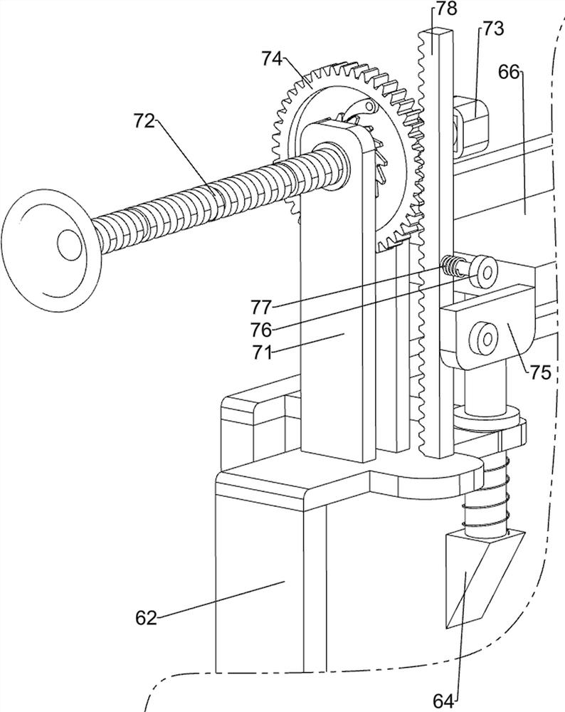
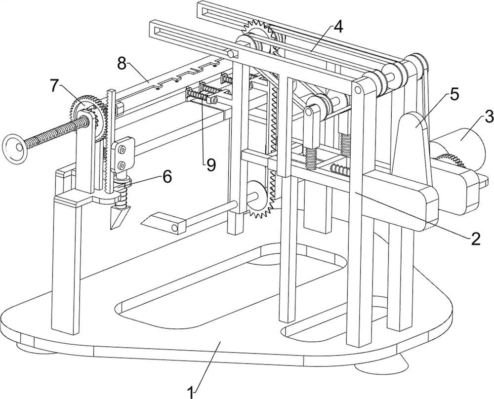
[0028] Such as figure 1 As shown, a dinosaur tail cutting machine for hand-made manufacturing includes a base 1, a frame 2, a motor 3, a moving transmission mechanism 4, a linear reciprocating mechanism 5, a lifting mechanism 6 and an intermittent feeding mechanism 7, and the base 1 A frame 2 is symmetrically arranged on the front side of the top, a motor 3 is installed on the outer wall of the right frame 2, a moving transmission mechanism 4 is arranged on the upper part between the two frames 2, and a straight line is arranged between the middle parts of the two frames 2. A reciprocating mechanism 5, a lifting mechanism 6 is arranged on the rear side of the top of the base 1, and an intermittent turning and feeding mechanism 7 is arranged on the lifting mechanism 6.
[0029] When it is necessary to use this equipment to cut the dinosaur tail for hand-figure manufacturing, first, the staff puts the dinosaur tail on the lifting mechanism 6, and makes the intermittent flip feed...
Embodiment 2
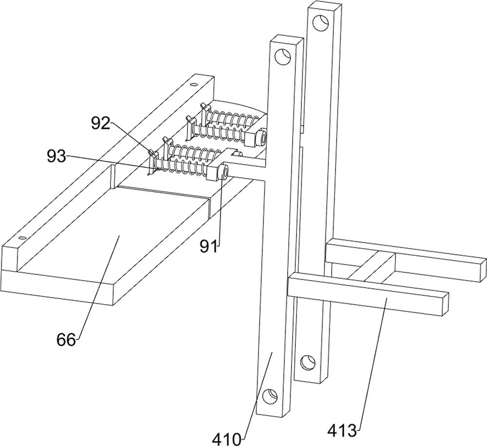
[0031] Such as figure 2 , image 3 , Figure 4 , Figure 5 and Figure 6As shown, a dinosaur tail cutting machine for hand-made manufacturing, on the basis of Embodiment 1, the mobile transmission mechanism 4 includes a first rotating shaft 41, a first belt 42, a first connecting shaft 43, a second belt 44, The first connecting rod 45, the first spring 46, the sleeve rod 47, the second rotating shaft 48, the limit pulley 49, the special-shaped connecting rod 410, the second connecting shaft 411, the cutter 412 and the H-type connecting rod 413, two frames 2 A first rotating shaft 41 is rotatably arranged between the upper front ends, and a straight-down first belt 42 is wound between the output shaft of the motor 3 and the adjacent end of the first rotating shaft 41. The upper ends of the two frames 2 are all opened with a belt away from the first rotating shaft 41. The word slot, the first connecting shaft 43 is slidingly arranged in the slot of the two frames 2, and the...
Embodiment 3
[0040] like Figure 7 and Figure 8 As shown, a dinosaur tail cutting machine for hand-made manufacturing, on the basis of Embodiment 1 and Embodiment 2, also includes a vertical limiting mechanism 8, and the vertical limiting mechanism 8 includes a fifth connecting rod 81, a fifth Six springs 82, top plate 83 and auxiliary pressure rod 84, the symmetrical sliding type at both ends of the L-shaped plate 66 is provided with the fifth connecting rod 81, the lower ends of the two fifth connecting rods 81 and the bottom of the L-shaped plate 66 are connected with the fifth connecting rod. Six springs 82, the sixth spring 82 is a compression spring, the sixth spring 82 is sleeved on the lower end of the fifth connecting rod 81, the top of the two fifth connecting rods 81 is provided with a top plate 83, the top plate 83 is located above the discharge block 73, Auxiliary pressing rods 84 are uniformly arranged on the front side of the top plate 83 , and the auxiliary pressing rods ...
PUM
 Abstract
Description
Claims
Application Information
 - R&D Engineer
- R&D Manager
- IP Professional
- Industry Leading Data Capabilities
- Powerful AI technology
- Patent DNA Extraction
Browse by: Latest US Patents, China's latest patents, Technical Efficacy Thesaurus, Application Domain, Technology Topic, Popular Technical Reports.
© 2024 PatSnap. All rights reserved.Legal|Privacy policy|Modern Slavery Act Transparency Statement|Sitemap|About US| Contact US: help@patsnap.com


