
Bottle cap printing system

A printing system and bottle cap technology, which is applied in printing, printing machines, rotary printing machines, etc., can solve the problems of reduced work efficiency, stuck loading and unloading, and high scrapping rate of bottle caps, so as to improve work efficiency, improve use efficiency, Reduce the effect of human assistance

Active Publication Date: 2021-04-16
浙江吉美食品科技有限公司
View PDF5 Cites 0 Cited by
  • Summary
  • Abstract
  • Description
  • Claims
  • Application Information

AI Technical Summary

Problems solved by technology

[0004] The existing bottle cap feeding operation is generally manual operation, but such an operation method is too labor-intensive, so that workers need to take frequent breaks, resulting in reduced work efficiency
[0005] The existing positioning mechanism screwed the bottle cap and the bottle body. Generally, a circular turntable is installed on the positioning mechanism to move the material. However, the existing circular turntable is not easy to install and disassemble, and the loading and unloading is prone to jamming. As a result, more manual assistance is still required in the production process
[0006] The existing bottle cap blanking device still has some disadvantages. The traditional bottle cap blanking device may deform or damage the bottle cap due to no buffer device when the bottle cap falls into the blanking device, resulting in a high scrapping rate of the bottle cap.

Method used


Image

  • Bottle cap printing system
  • Bottle cap printing system
  • Bottle cap printing system

Examples


Embodiment Construction

[0036] The specific embodiment of the specific solution of the present invention will be further elaborated in conjunction with the accompanying drawings.

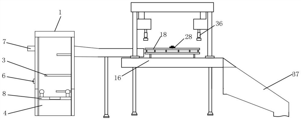
[0037] As shown in the figure, a bottle cap printing system includes a feeding mechanism, a positioning mechanism and a feeding mechanism. Institutional connections.

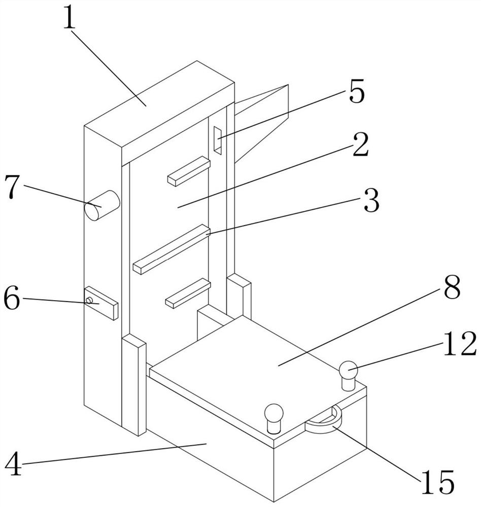
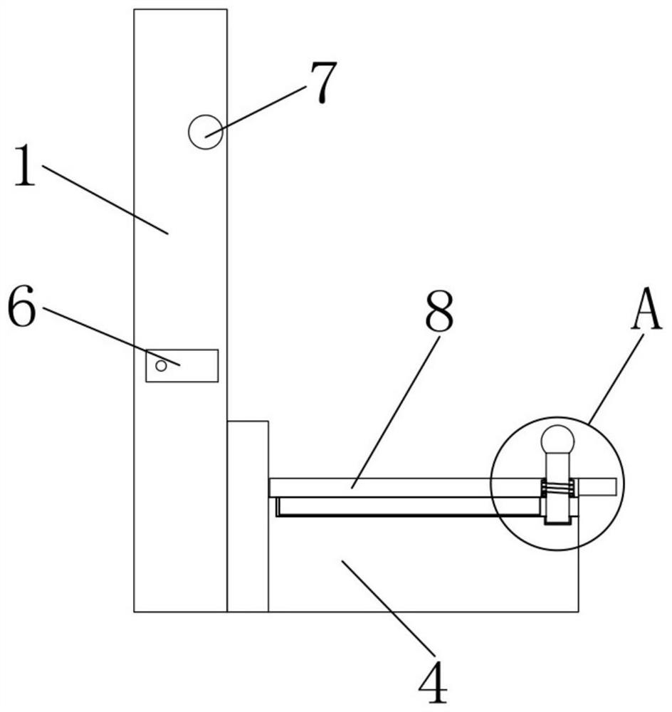
[0038] The feeding mechanism includes a fixed seat 1, a conveyor belt 2 is installed inside the fixed seat 1, and multiple groups of transport strips 3 are fixed on the outer wall of the conveyor belt 2, a storage bin 4 is installed at the lower end of the fixed seat 1, and a discharge port is opened at the upper end of the fixed seat 1 5. A control switch 6 is installed on the front end of the fixed seat 1, and a fan 7 is installed above the control switch 6;

[0039] During use, the conveyor belt 2 and the fan 7 are operated by the control switch 6. At this time, the transport bar 3 will carry the bottle caps stored in the warehouse 4 upwards. When the tr...


PUM


Abstract

The invention discloses a bottle cap printing system. The bottle cap printing system involves a feeding mechanism, a positioning mechanism and a discharging mechanism, wherein the feeding mechanism is connected with the positioning mechanism through a conveying belt, the other side of the positioning mechanism is connected with the discharging mechanism through a discharging port, a placing bin is installed at the lower end of a fixing base of the feeding mechanism, and the upper end of the fixing base is provided with the discharging port and a fan; the positioning mechanism is provided with a limiting anti-collision assembly; and the discharging mechanism is provided with a buffer sliding groove assembly. According to the bottle cap printing system, through improvement of the three most critical mechanisms, the overall printing production efficiency is high, manual assistance is reduced, the system mechanism is not too complex, and the cost is low; the feeding mechanism avoids manual operation of workers, and improves the working efficiency of the bottle cap printing system; when the positioning mechanism does not need to be mounted and dismounted, the positioning mechanism has good mistaken collision prevention performance; and the discharging mechanism enables bottle caps to have enough buffering force for protection so that the bottle cap printing system can guarantee the normal operation of a discharging device body, and effectively improves the use efficiency of the bottle cap printing system.

Description

technical field [0001] The invention relates to the field of bottle cap production, in particular to a bottle cap printing system. Background technique [0002] The bottle cap is used to seal the bottle. According to different functions, there are bottle caps with different shapes and different operation methods. [0003] In the production process of bottle caps, it is necessary to have different products and manufacturers to print the text and patterns on the surface of the bottle caps. The printing process usually includes a feeding mechanism, a positioning mechanism and a feeding mechanism, and printing is performed after the bottle cap is positioned. [0004] The existing bottle cap feeding operation is generally performed manually, but such an operation method is too labor-intensive, so that workers need to take frequent breaks, resulting in reduced work efficiency. [0005] The existing positioning mechanism screwed the bottle cap and the bottle body. Generally, a ci...

Claims


Application Information

Patent Timeline
Patent Type & Authority Applications(China)
IPC IPC(8): B41F17/16B65G11/20
Inventor 郑雅丹冯魏杨鹏
Owner 浙江吉美食品科技有限公司
Learn More