
Anti-breakage and anti-loosening rope protection device for elevator

A protection device and anti-fracture technology, which is applied in hoisting devices, elevators in buildings, transportation and packaging, etc., can solve problems affecting the normal use of elevators and breakage of traction ropes, so as to prevent breakage and reduce mechanical stress. Dynamic loss, reduce the effect of rigid braking

Inactive Publication Date: 2021-04-16
CIVIL ELEVATOR
View PDF8 Cites 0 Cited by
  • Summary
  • Abstract
  • Description
  • Claims
  • Application Information

AI Technical Summary

Problems solved by technology

[0004] The purpose of the present invention is to provide an elevator anti-breakage and anti-loosening rope protection device to solve the problem that the existing elevator protection device proposed in the background technology is used because the connection of the traction rope is too tight. If appropriate adjustments are made in time, the traction rope will break, which will affect the normal use of the elevator

Method used


Image

  • Anti-breakage and anti-loosening rope protection device for elevator
  • Anti-breakage and anti-loosening rope protection device for elevator
  • Anti-breakage and anti-loosening rope protection device for elevator

Examples


Embodiment 1

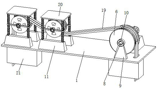
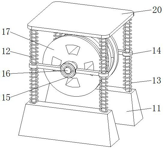
[0026] see Figure 1-6 , the present invention provides a technical solution: an anti-breakage and anti-loosening rope protection device for an elevator, comprising a base plate 1, a fixed base 11 is fixedly installed on the top of the base plate 1, a fixed rod 12 is fixedly installed on the top of the fixed base 11, and the fixed rod The outer movable socket of 12 is provided with a position spring 13, the external movable socket of the fixed rod 12 is provided with a socket rod 14, the inside of the socket rod 14 is fixedly installed with a socket bearing 15, and the inside of the socket bearing 15 is fixedly installed with a guide Rod 16, one side of the guide rod 16 is fixedly equipped with a guide wheel 17, the outside of the guide wheel 17 is provided with a guide groove 18, the inside of the guide groove 18 is equipped with a traction rope 19, and the bottom of the bottom plate 1 is fixedly installed with a brake box 21. The top and bottom of the bottom plate 1 are prov...

Embodiment 2

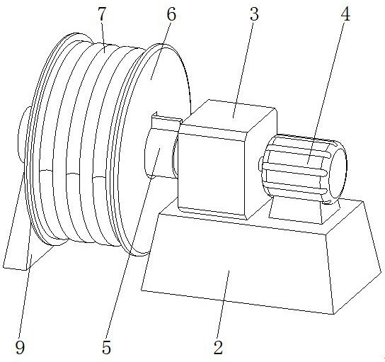
[0029] like Figure 1-6As shown, on the basis of Embodiment 1, the present invention provides a technical solution: the top of the bottom plate 1 is fixedly installed with a mounting base 2, the top of the mounting base 2 is fixedly mounted with a reducer 3, and the top of the mounting base 2 is fixed A rotating motor 4 is installed, and the output end of the rotating motor 4 runs through the reducer 3 and extends to its interior. The side of the reducer 3 far away from the rotating motor 4 is movably installed with a rotating rod 5 , and the outer part of the rotating rod 5 is movably sleeved with a traction The pulley 6 and the outside of the traction wheel 6 are provided with a traction groove 7, and the side of the traction wheel 6 away from the rotating rod 5 is fixedly installed with a rotating rod 8, and the top of the bottom plate 1 is fixedly installed with a support frame 9, and the top of the support frame 9 The rolling bearing 10 is fixedly installed, and the end o...

Embodiment 3

[0032] like Figure 1-6 As shown, on the basis of Embodiment 1 and Embodiment 2, the present invention provides a technical solution: there are four fixed bases 11, and the four fixed bases 11 are divided into two groups and symmetrically installed on the top of the bottom plate 1 , there are four fixed rods 12, the four fixed rods 12 are rectangular and fixedly installed on the top of a group of fixed bases 11, the top of the four fixed rods 12 is fixedly installed with a top plate 20, there are two suitable springs 13, two suitable The position springs 13 are respectively positioned above and below the socket rod 14, and the front and rear sides of the guide wheel 17 are fixedly equipped with a guide rod 16, and the end of the guide rod 16 away from the guide wheel 17 runs through the sleeve bearing 15 and is fixedly installed inside it. , there are two guide wheels 17, multiple traction ropes 19, multiple traction ropes 19 are movably installed above the traction groove 7, ...


PUM


Abstract

The invention discloses an anti-breakage and anti-loosening rope protection device for an elevator. The anti-breakage and anti-loosening rope protection device comprises a bottom plate, fixed bases are fixedly installed at the top of the bottom plate, fixed rods are fixedly installed at the top of the fixed base, the outer portions of the fixed rods are movably sleeved with adaptive springs, the outer portions of the fixed rods are movably sleeved with sleeving rods, and sleeving bearings are fixedly installed in the sleeving rods; and guide rods are fixedly installed in the sleeving bearings, guide wheels are fixedly installed on one sides of the guide rods, guide grooves are formed in the outer portions of the guide wheels, traction ropes are movably installed in the guide grooves, and brake boxes are fixedly installed at the bottom of the bottom plate. The anti-breakage and anti-loosening rope protection device has the beneficial effects that the ends, away from a traction wheel, of the installed traction ropes penetrate through the lower portion of one guide wheel and the lower portion of the other guide wheel, so that when the traction ropes are too tight, the traction ropes deviate upwards through the adaptive springs on the two sides of the first guide wheel so as to be relieved, and the traction ropes deviate downwards through the adaptive springs on the two sides of the second guide wheel so as to be relieved.

Description

technical field [0001] The invention belongs to the technical field of elevator protection devices, and in particular relates to an anti-breakage and anti-loosening rope protection device for elevators. Background technique [0002] Elevator is a kind of vertical elevator powered by electric motor, equipped with box-shaped gondola, which is used for multi-storey buildings to take people or carry goods. There is also a step type, and the tread plate is installed on the crawler belt to run continuously, commonly known as an escalator or a moving walk. Fixed lifting equipment serving specified floors. A vertical lift has a car that runs between at least two vertical columns of rigid guide rails. The size and structure of the car are convenient for passengers to enter and exit or to load and unload goods. It is customary to use elevator as a general term for vertical transportation in buildings regardless of its driving mode. [0003] If all the ropes of the car are broken w...

Claims


Application Information

Patent Timeline
Patent Type & Authority Applications(China)
IPC IPC(8): B66B5/12B66B7/10B66B11/08B66D5/16B66D5/28F16F15/067
Inventor 宋良英沈怡萍许开新张嫣
Owner CIVIL ELEVATOR
Learn More