Liquid storage assembly, feeding device with liquid storage assembly and multi-barrel washing machine
A component and liquid storage technology, which can be applied to other washing machines, washing devices, household appliances, etc., and can solve the problems of non-removable clothes treatment agent boxes.
- Summary
- Abstract
- Description
- Claims
- Application Information
AI Technical Summary
Problems solved by technology
Method used
Image
Examples
Embodiment 1
[0101] Embodiment 1 Delivery device
[0102] 【overall arrangement】
[0103] The dispensing device of the present invention is a treatment agent dispensing equipment installed on washing equipment. The specific washing equipment can be washing equipment such as dishwashers and washing machines, and the treatment agent can be laundry treatment agents or other treatment agents. The present invention It does not limit its type.
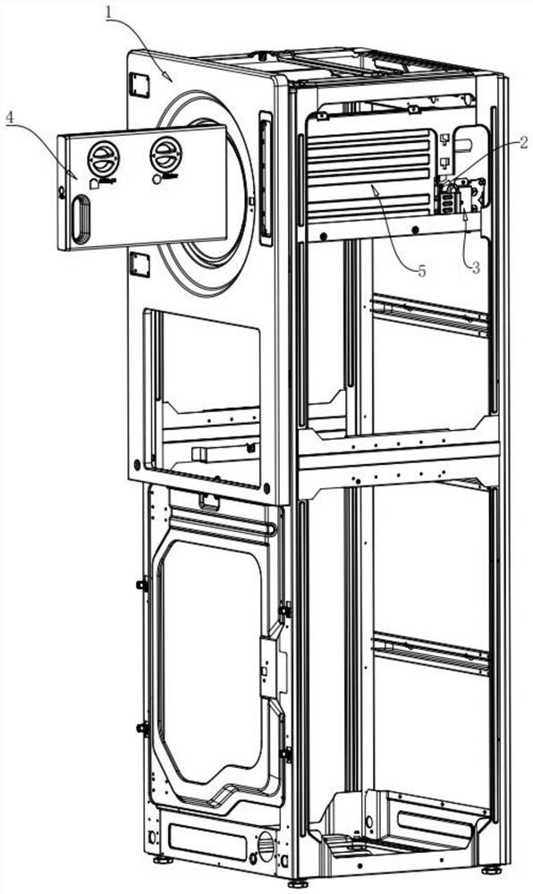
[0104] Such as figure 1 As shown, in this embodiment, the dispensing device is preferably arranged on a multi-tub washing machine, and the multi-tub washing machine is provided with a plurality of laundry processing tubs from top to bottom. The specific use of multiple laundry processing buckets can be a combination of buckets with different laundry processing functions such as washing, dehydration, drying, disinfection, etc., but preferably at least has a washing function. In addition, the washing method may be a combination of washing tubs of differe...
Embodiment approach 1
[0137] Such as Figure 7a , 7b , 7c, 7d, the preferred locking / ejection assembly includes a locking assembly and an ejection assembly.
[0138] Such as Figure 7a As shown, the locking assembly 71 of this embodiment is arranged on the front end of the liquid storage box 4 and the installation box 4; the locking assembly 71 includes a first locking buckle 711, a second locking buckle 712, a first locking buckle Tightening groove 713 and second locking groove 714; the locking buckle is arranged on the front end of the liquid storage box 4, preferably, one upper and lower position respectively; the locking groove is arranged on the front end of the installation box 5, preferably, the upper and lower one each. Wherein the first locking buckle 711 corresponds to the first locking slot 713; the second locking buckle 712 corresponds to the second locking slot 714; when the liquid storage box 4 is pushed into the installation box 5, it is locked The buckle cooperates with the lock...
Embodiment approach 2
[0142] Such as Figure 7c and 7d As shown, the preferred locking / ejecting assembly includes a mechanical latch and a rebounding assembly, wherein:
[0143] By using the mechanical lock, the user can lock the liquid storage box 4 to the installation box 5 or release it from the installation box 5 by pressing the front cover 43 of the liquid storage box once. Preferably, the mechanical lock includes: a lock 751 and a lock lock position 752, the lock 751 is arranged on the rear cover 53 of the installation box or on the rear cover 44 of the liquid storage box; the lock lock position 752 and the lock The position of 751 corresponds, and it is arranged on the back cover 44 of the liquid storage box or on the back cover 53 of the installation box; the lock 751 can be a lock with a wedge-shaped buckle, and there is a lock 751 on the locking position 752 of the lock. Fitting recessed holes.
[0144] The ejection assembly includes a release button 72, a rebound top piece 731, a spri...
PUM
 Abstract
Description
Claims
Application Information
 - R&D
- Intellectual Property
- Life Sciences
- Materials
- Tech Scout
- Unparalleled Data Quality
- Higher Quality Content
- 60% Fewer Hallucinations
Browse by: Latest US Patents, China's latest patents, Technical Efficacy Thesaurus, Application Domain, Technology Topic, Popular Technical Reports.
© 2025 PatSnap. All rights reserved.Legal|Privacy policy|Modern Slavery Act Transparency Statement|Sitemap|About US| Contact US: help@patsnap.com


