Rotary drive device

a rotary drive and drive shaft technology, applied in the direction of ignition automatic control, program control, instruments, etc., can solve the problems of difficult to improve the precision of movement, linear movement, difficult to improve the positioning accuracy of high-precision robot arms, etc., to achieve increased movement precision, high precision, and suppressed vibration of robot arms

Active Publication Date: 2011-08-25
CANON KK
View PDF21 Cites 34 Cited by
  • Summary
  • Abstract
  • Description
  • Claims
  • Application Information

AI Technical Summary

Benefits of technology

[0010]According to the present invention, because the rotation angle of the rotation shaft of the reduction gear is controlled according to the detection result of the second angle-detecting unit, even if the rotation position of the rotation shaft of the reduction gear is shifted with respect to the rotation shaft of the servo motor, due to insufficient strength or distortion of the reduction gear, it is possible to position the rotation shaft of the reduction gear with high precision. This increases the precision of movement, such as linear movement, of the robot arm. Furthermore, because the torque based on the torsional stiffness of the reduction gear is calculated using the detection results of the first angle-detecting unit and second angle-detecting unit, and the torque control is performed according to this calculation result, the vibration of the robot arm can be suppressed without using a torque sensor. Thus, it is possible to prevent extension of the settling time due to insufficient strength of the reduction gear, and it is possible to reduce the time before starting the operation of the robot arm.

Problems solved by technology

However, because the rotary drive device rotationally drives the object to be driven via the reduction gear, an inner mechanism of the reduction gear may be deformed or distorted, due to insufficient strength, by the torque acting on the rotation shaft of the reduction gear.
In the conventional rotary drive device, if the rotation shaft of the reduction gear is shifted from the ideal position due to twisting like this, high-precision positioning becomes difficult.
Accordingly, it is difficult to improve the precision of movement, such as linear movement, of robot arms.
Furthermore, vibration of the rotation shaft of the reduction gear cannot be suppressed because of insufficient strength of the reduction gear.
More specifically, the provision of an origin sensor on the rotation shaft of the reduction gear, as in the above-described conventional rotary drive device, is not enough for high-precision positioning, because it simply detects the position of the origin and, thus, the resolution of position detection is insufficient.
Furthermore, even if the torque sensor is provided on the rotation shaft of the reduction gear, as in the above-described conventional rotary drive device, it is impossible to detect the amount of deformation of the inner mechanism or the amount of shift of the rotation position of the rotation shaft, due to distortion, caused by the torque acting on the inner mechanism via the rotation shaft of the reduction gear.
Therefore, it is impossible to position the rotation shaft of the reduction gear with high precision.

Method used


Image

  • Rotary drive device
  • Rotary drive device
  • Rotary drive device

Examples


first embodiment

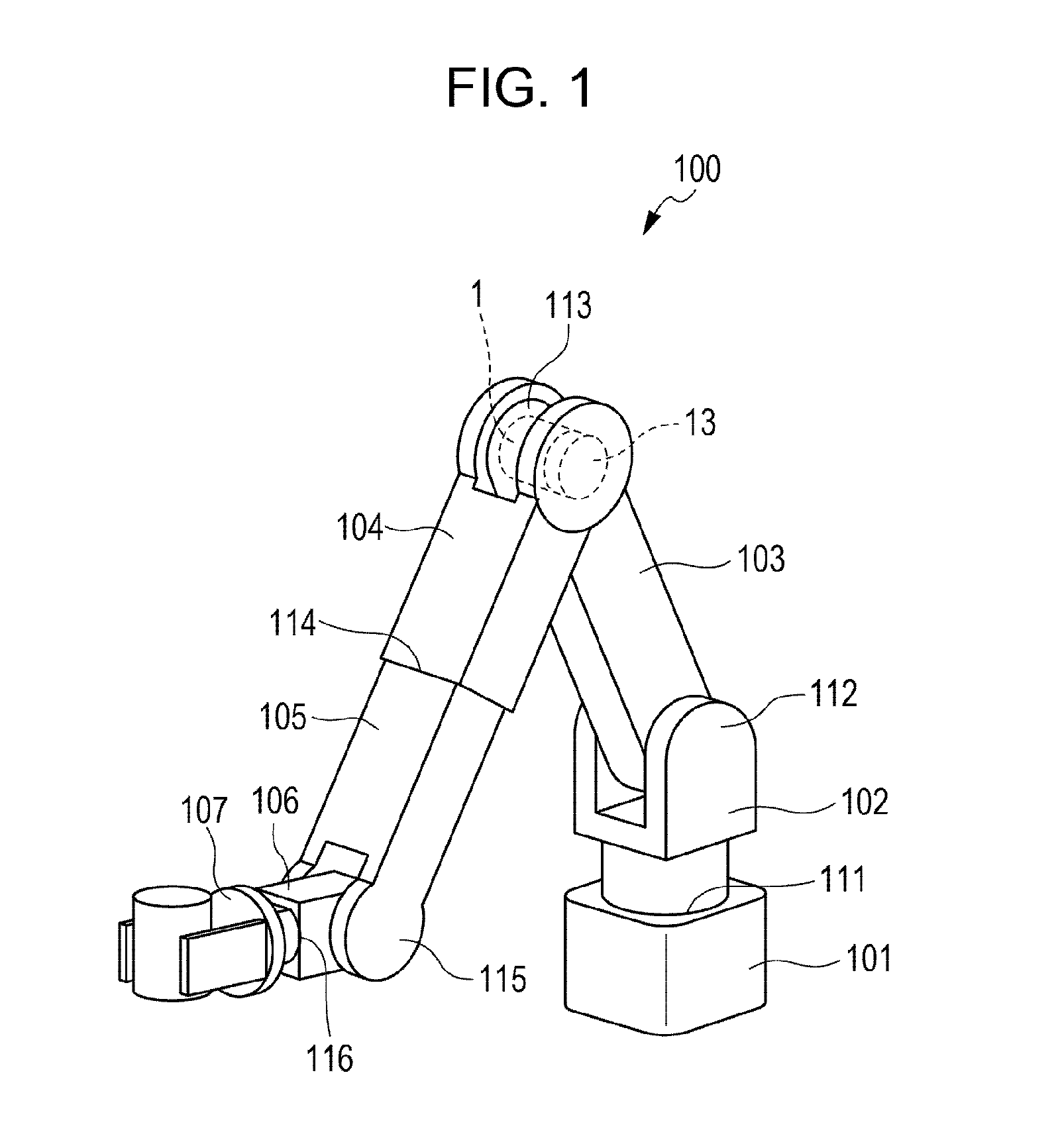
[0017]FIG. 1 is a perspective view of a robot arm according to a first embodiment of the present invention. A robot arm 100 includes a base 101 fixed to an operation table, a swivel portion 102 that is supported by the base 101 in a manner capable of swiveling, and a first link 103 that is supported by the swivel portion 102 so as to be capable of swinging. Furthermore, the robot arm 100 includes a second link 104 that is supported by the first link 103 so as to be capable of swinging, and a third link 105 that is supported by the second link 104 so as to be capable of advancing and retracting. Furthermore, the robot arm 100 includes a tip link 106 that is supported by the third link 105 so as to be capable of swinging and a hand 107 provided on the tip link 106. These components are joined to one another by a first joint portion 111, a second joint portion 112, a third joint portion 113, a fourth joint portion 114, a fifth joint portion 115, and a sixth joint portion 116. Each of t...

second embodiment

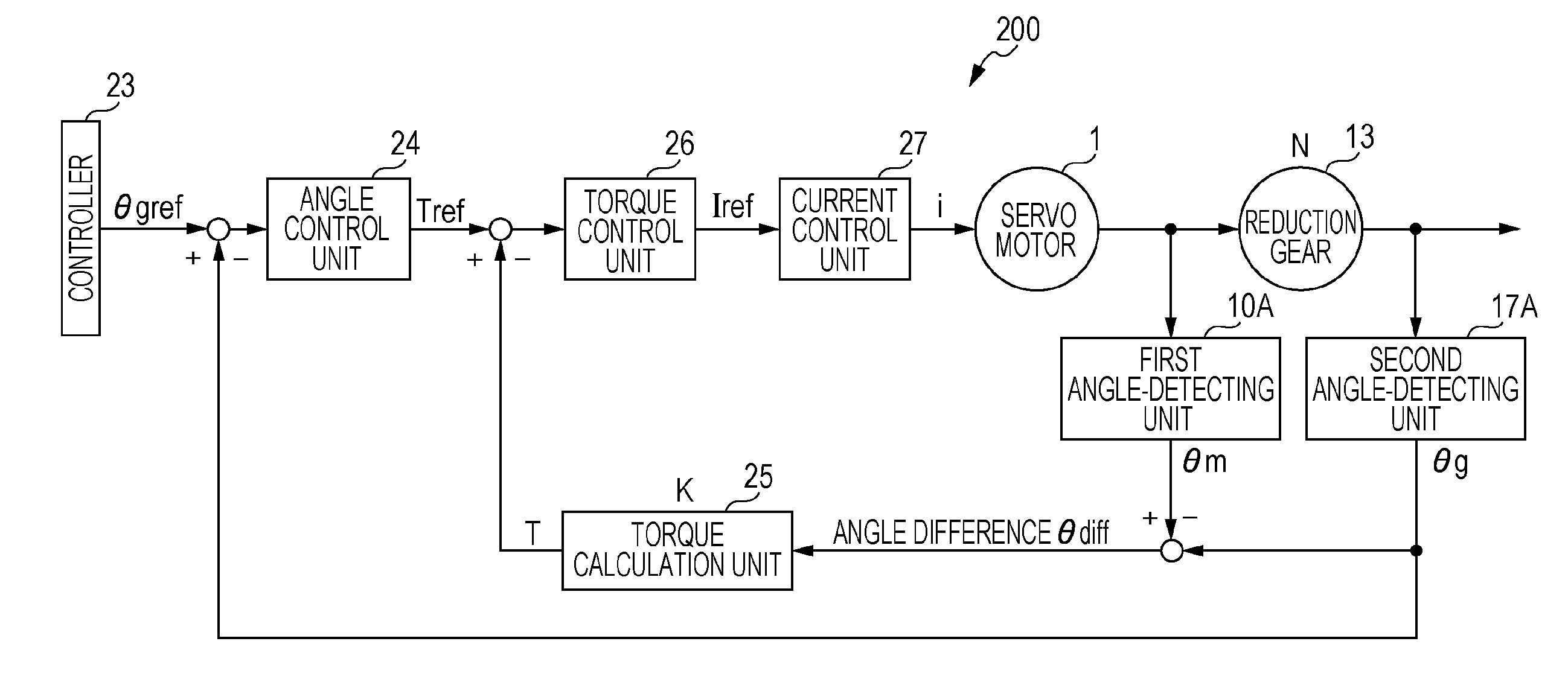
[0033]Next, a rotary drive device 200A according to a second embodiment will be described with reference to FIG. 4. FIG. 4 is a control block diagram of the rotary drive device 200A according to the second embodiment of the present invention. In the second embodiment, the controller 23A not only outputs the angle reference value θgref, which is the target rotation angle of the rotation shaft 20 of the reduction gear 13, but also selects one of a first operation mode A and a second operation mode B. The selection of the operation mode by the controller 23A may be performed by a user operating an input device (not shown) or according to an operation program for moving the robot arm 100 (FIG. 1).

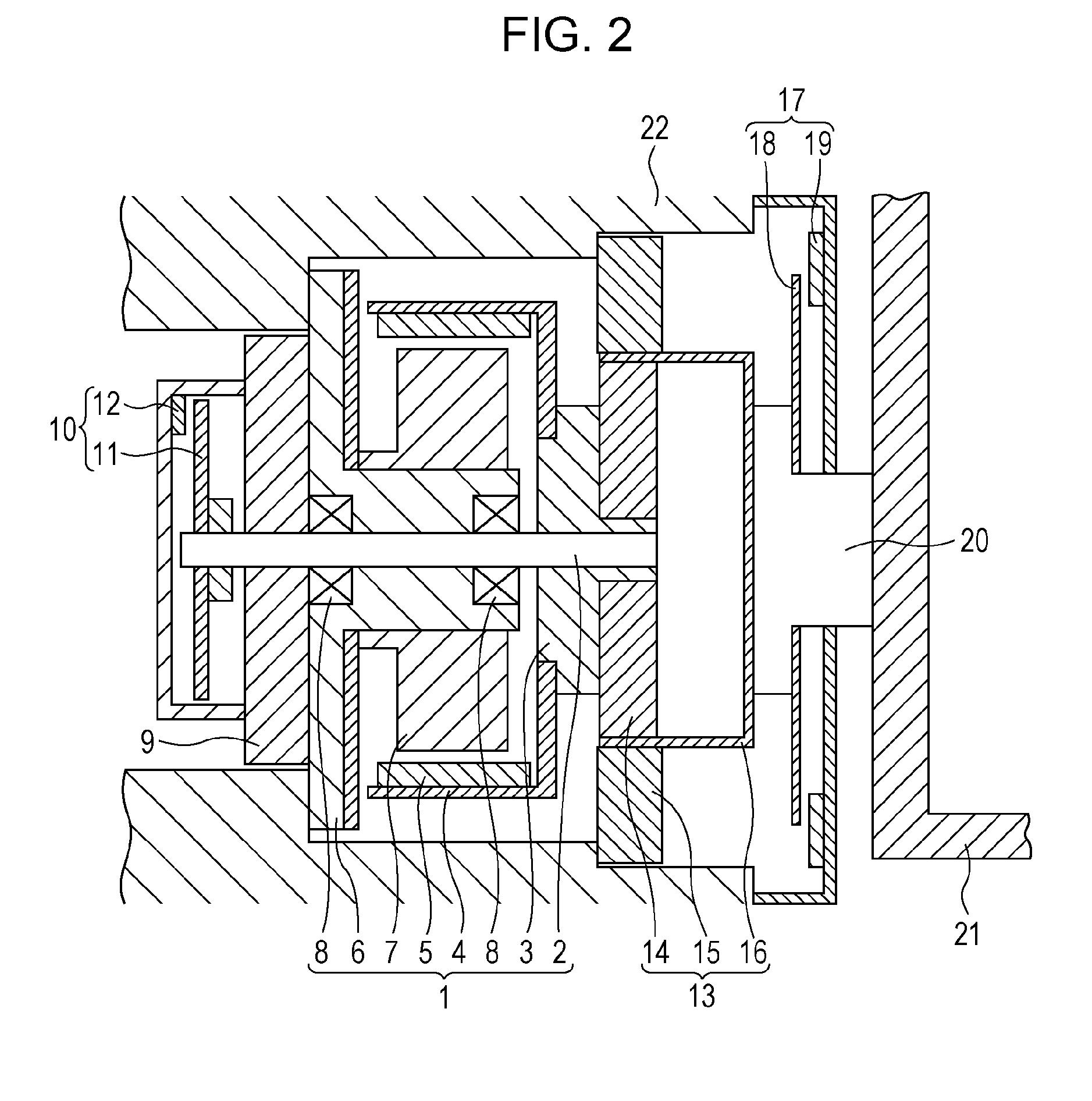
[0034]Furthermore, the rotary drive device 200A includes the servo motor 1, the reduction gear 13, the first angle-detecting unit 10A, the second angle-detecting unit 17A, the torque calculation unit 25, the torque control unit 26, and the current control unit 27, which have the same configurat...


PUM


Abstract

A first angle-detecting unit outputs a first rotation angle according to the rotation angle of a rotation shaft of a servo motor. A second angle-detecting unit outputs a second rotation angle according to a rotation angle of a rotation shaft of a reduction gear. A torque calculation unit calculates the torque acting on the rotation shaft of the reduction gear according to the angle difference between the first rotation angle and the second rotation angle. An angle-control unit generates a torque reference value according to the difference between the angle reference value and the second rotation angle. A torque control unit generates a current reference value according to the difference between the torque reference value and the torque.

Description

BACKGROUND OF THE INVENTION[0001]1. Field of the Invention[0002]The present invention relates to rotary drive devices for driving joints, such as links and hands, of a robot arm, and, more specifically, it relates to rotary drive devices for rotationally driving joints via reduction gears.[0003]2. Description of the Related Art[0004]A typical conventional rotary drive device for driving a link or hand of a robot arm uses an AC or DC servo motor and is connected to the object to be driven, with a reduction gear provided on the output side of the motor to obtain a high-output torque. In recent years, robot arms are required to achieve higher precision, higher speed, and higher output. Japanese Patent Laid-Open No. 2006-141101 proposes a rotary drive device that uses a reduction gear, in which the position of the origin with respect to the rotation shaft of the reduction gear is detected. Furthermore, Japanese Patent Laid-Open No. 5-252779 discloses a control structure that controls th...

Claims


Application Information

Patent Timeline
Patent Type & Authority Applications(United States)
IPC IPC(8): G05B11/00H02P29/00
CPCB25J9/1633B25J9/1641G05B2219/49197G05B2219/39186G05B2219/37297G05B2219/42093G05B2219/42097
Inventor NAKASUGI, MIKIO
Owner CANON KK
Why Eureka
Try Eureka