
Intelligent concrete vibrating device for lock chamber wall

A vibrating device and concrete technology, which are applied in ship lifting devices, ship locks, climate change adaptation, etc., can solve the problems of slow manual vibrating and vibrating progress, inability to effectively vibrate in dead corners, threats to workers' life safety, etc., and reduce labor. The effect of quantity loss, large engineering quantity and high utilization rate

Pending Publication Date: 2021-04-16
安徽建工路港建设集团有限公司 +1
View PDF0 Cites 3 Cited by
  • Summary
  • Abstract
  • Description
  • Claims
  • Application Information

AI Technical Summary

Problems solved by technology

[0013] For the vibration of the lock chamber wall of general ship locks, due to the limitation of the construction environment on site, workers can only go deep into the lock chamber wall formwork with a depth of more than ten meters, and carry out the working method of vibrating while pouring. During summer work, the lock chamber wall formwork The internal temperature is extremely high, which will pose a threat to the life safety of workers, and because the lock chamber wall adopts a dock structure, manual vibration cannot effectively vibrate some dead corners, so there will be some problems in the quality and safety factor of the lock chamber wall, and at the same time Manual vibration is used to vibrate slowly, the construction efficiency is low, and the labor consumption is large. Moreover, the inside of the lock chamber wall is full of steel bars, and there is no platform for workers to work. Workers can only work with safety ropes. May cause safety accident

Method used


Image

  • Intelligent concrete vibrating device for lock chamber wall
  • Intelligent concrete vibrating device for lock chamber wall
  • Intelligent concrete vibrating device for lock chamber wall

Examples


Embodiment Construction

[0049] The technical solutions of the present invention will be further described in detail below in conjunction with specific embodiments. In the description of the present invention, unless otherwise specified, "plurality" means two or more.

[0050] There is randomness in the guarantee of the quality of the lock chamber wall. Due to the limited skills of the construction personnel and the dock-type structure of the lock chamber wall, it is impossible to vibrate every part of the lock chamber wall with the existing equipment and operators; During the process, the construction personnel need to go deep into the bottom of the lock chamber wall more than ten meters deep to vibrate, which is very prone to safety accidents; the progress of manual vibration is slow, the construction efficiency is low, and the labor consumption is large. The purpose of the present invention is to provide a An intelligent vibrating device for the concrete of the lock chamber wall is used to solve th...


PUM


Abstract

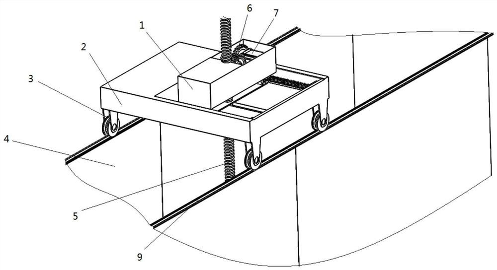
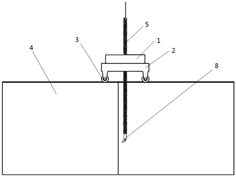
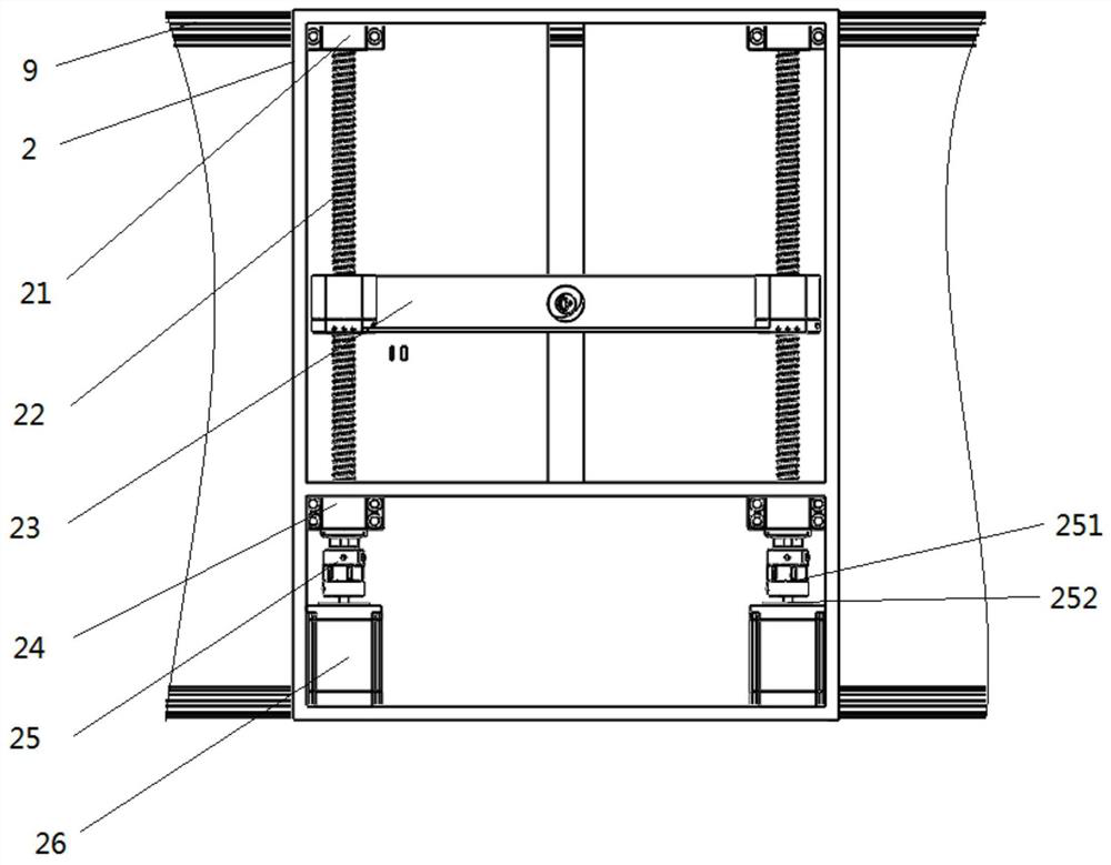
The invention is applicable to the field of construction equipment, and particularly relates to a lock chamber wall concrete intelligent vibrating device which comprises X-direction walking systems, the walking devices are distributed on the machine box in an array mode, the walking devices are meshed on the template track, and the template track is used for driving the machine box to walk in the X direction; a Y-direction walking system which is provided with a plurality of sets of reciprocating periodic moving structures in the machine box, the reciprocating periodic moving structures are connected to the sliding block machine box, and the reciprocating periodic moving structures are used for driving the sliding block machine box to walk in the Y direction; a Z-direction walking system which is provided with a worm driven by a turbine set structure to move; a three-axial-degree-of-freedom walking system of the X-direction walking system, the Y-direction walking system and the Z-direction walking system replaces workers to conduct construction, and life risks, caused by misoperation, of the workers are prevented; and a machine plans a route, so that large deviation is avoided.

Description

technical field [0001] The invention relates to the field of construction equipment, in particular to an intelligent vibrating device for concrete of a lock chamber wall. Background technique [0002] For mechanical vibration, it is mainly divided into the following categories: [0003] 1) Internal vibrator (plug-in vibrator) [0004] The disadvantage is that it is not suitable for structures and components with particularly dense reinforcement and thin thickness, and the lock chamber wall is just such a component; and limited by the vibration time, the general working time is 2.5-3s, and the high-frequency vibration can reduce the time. But at least more than 10s, the time cannot be fully and accurately controlled during work. If the time is too short, the concrete will not be easily vibrated, and if the time is too long, it will lead to segregation, which will directly affect the quality of the lock chamber wall, and generally The on-site construction personnel of the lo...

Claims


Application Information

Patent Timeline
Patent Type & Authority Applications(China)
IPC IPC(8): E02C1/00E02D15/02
CPCY02A10/30
Inventor 张俊苏颖浦玉学王静峰余梦郑金辉刘春梅过令郭大锤李长春陈标张宾杨欢
Owner 安徽建工路港建设集团有限公司
Learn More