Waterproof canopy installed based on basement entrance and exit structure

A technology for entrances, exits and basements, applied in building structures, building components, circuit devices, etc., can solve the problems of poor aesthetic effect, poor lighting, and poor strength, and achieve easy popularization, long use time, and extended use. effect of life

Active Publication Date: 2021-04-16
宿迁市高速铁路建设发展有限公司 +1
View PDF5 Cites 0 Cited by
  • Summary
  • Abstract
  • Description
  • Claims
  • Application Information

AI Technical Summary

Problems solved by technology

[0006] The purpose of the present invention is to provide a waterproof canopy installed based on the structure of the entrance and exit of the basement. Through the sunshade device, it can be adjusted and used according to the different seasons, and the two side panels of the canopy are bent-shaped structures and placed at the bends There are flower pots, which solve the existing waterproof canopy. One uses a glass roof for better light transmission, but the sun is too strong in summer and autumn and does not have a sunshade function. The other uses a solid roof for sunshade , but the light is not good, it needs supplementary light, it is not economical and environmentally friendly, and the water delivery effect is not strong, so that the top of the waterproof awning is under a lot of pressure and is easy to be damaged, and the function of the waterproof awning is relatively single, the aesthetic effect is not strong, not too Questions in line with the concept of green environmental protection

Method used


Image

  • Waterproof canopy installed based on basement entrance and exit structure
  • Waterproof canopy installed based on basement entrance and exit structure
  • Waterproof canopy installed based on basement entrance and exit structure

Examples


Embodiment Construction

[0031] The following will clearly and completely describe the technical solutions in the embodiments of the present invention with reference to the accompanying drawings in the embodiments of the present invention. Obviously, the described embodiments are only some, not all, embodiments of the present invention. Based on the embodiments of the present invention, all other embodiments obtained by persons of ordinary skill in the art without creative efforts fall within the protection scope of the present invention.

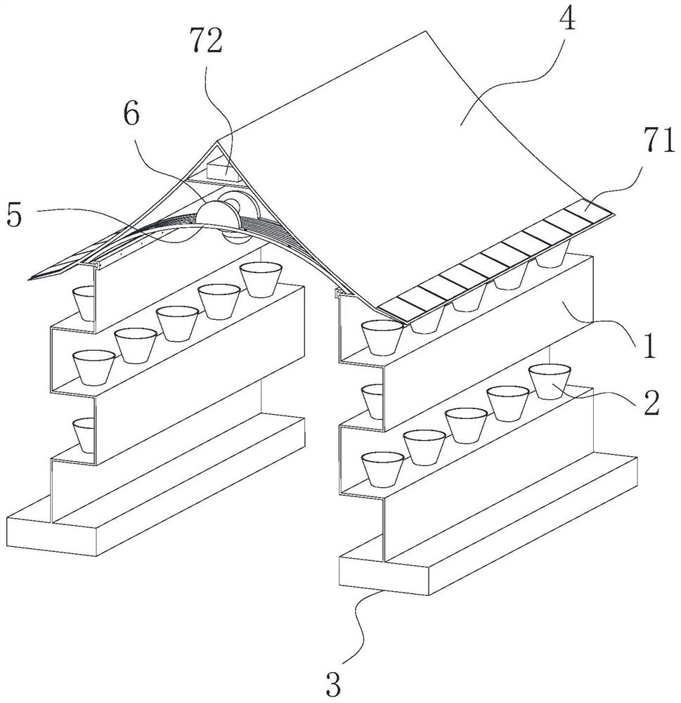
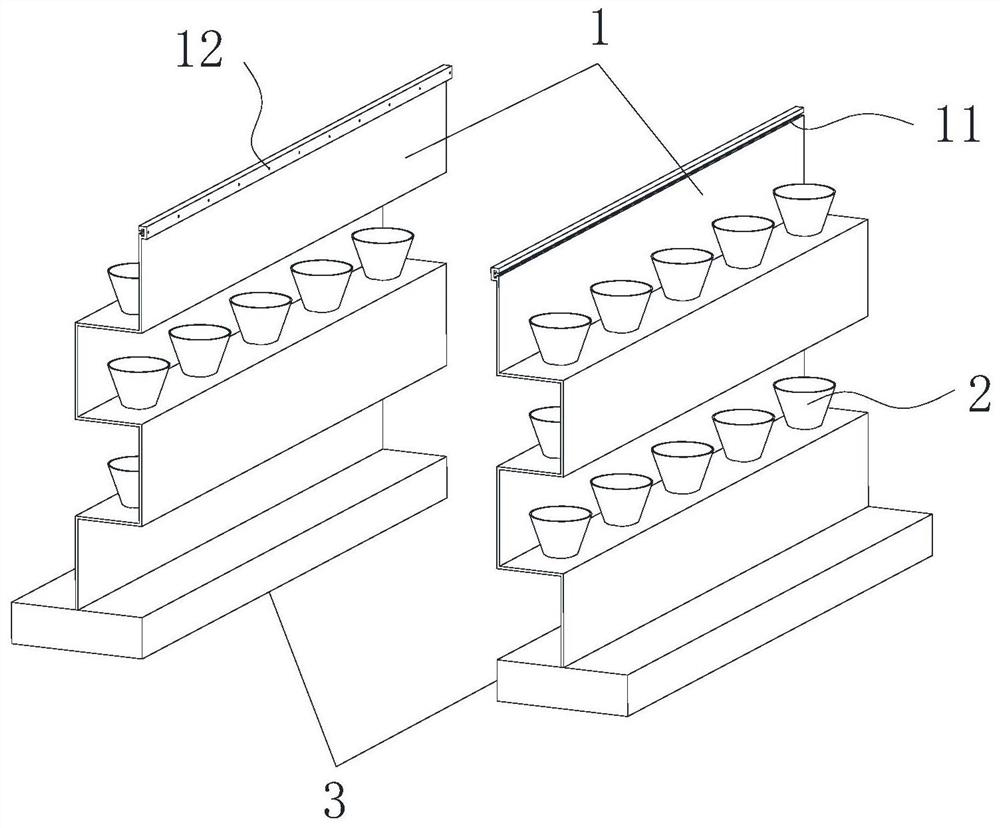
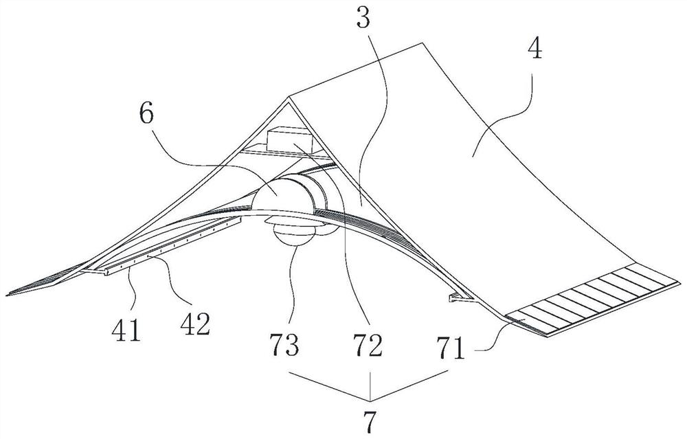
[0032] see Figure 1-6 As shown, the present invention is a waterproof canopy installed based on the structure of the entrance and exit of the basement, including a folded side panel 1, a flower pot 2, a base 3, a herringbone glass outer shed 4, an arc-shaped glass inner shed 5, a sunshade device 6 and lighting Mechanism 7, a flowerpot 2 is placed at the turning point of the folded side panel 1, a base 3 is fixed on the bottom of the folded side panel 1, and the ba...


PUM


Abstract

The invention discloses a waterproof canopy installed based on a basement entrance and exit structure, and relates to the technical field of basement entrance waterproofing. The canopy comprises a folding type side plate, a herringbone glass outer shed, an arc-shaped glass inner shed and sun shading devices, wherein the arc-shaped glass inner shed is fixed to the bottom side of the interior of the herringbone glass outer shed, and the sun shading devices are detachably connected to the top face of the arc-shaped glass inner shed through screws; and a fixed semi-ring plate, a movable semi-ring plate, sun shading cloth and an electric hydraulic push rod jointly constitute each sun shading device, the sun shading cloth is connected between the fixed semi-ring plate and the movable semi-ring plate, and the electric hydraulic push rod is connected between the parts, located at the top of the sun shading cloth, of the fixed semi-ring plate and the movable semi-ring plate. The waterproof canopy is provided with the sun shading devices, when the waterproof canopy is used in winter, the sun shading devices do not work, when the waterproof canopy is used in summer, the sun shading cloth in the two sun shading devices is unfolded at the same time, and thus the top of the arc-shaped glass inner shed can be covered, perfect sunshade can be achieved, the waterproof canopy is adjusted and used according to different seasons, and the waterproof canopy is very convenient, practical and convenient to popularize and use.

Description

technical field [0001] The invention belongs to the technical field of basement entrance waterproofing, in particular to a waterproof canopy installed based on the structure of basement entrances and exits. Background technique [0002] At present, the current basement entrance waterproof structure generally erects a waterproof canopy on the top of the basement entrance. It can effectively block rainwater and prevent rainwater from flowing into the basement entrance and causing water accumulation inside the basement. Now the style of the canopy at the basement entrance in many places It can be described as diverse, but it still has the following disadvantages in actual use: [0003] 1. The existing waterproof canopy, one uses a glass roof for better light transmission, but the sun is too strong in summer and autumn, and does not have the sunshade function; the other uses a solid roof for sunshade, but the light is not enough Well, it needs supplementary light, which is not ...

Claims


Application Information

Patent Timeline
Patent Type & Authority Applications(China)
IPC IPC(8): E04H1/12E04B2/00E04C2/32E04B7/10E04D3/06E04D13/18E04F10/02H02J7/35A01G9/02
Inventor 罗东志黄雪林王深山唐敏张俊高新博杨波鲍金凯
Owner 宿迁市高速铁路建设发展有限公司
Why Eureka
Try Eureka