
Welding-free pin shaft and stop device

A stop device, welding-free technology, applied in the direction of connecting components, mechanical equipment, etc., can solve the problems of poor welding performance, complex stress situation, and pin stop failure, etc., to eliminate the risk caused by weld cracking, The effect of simple manufacturing process and improved reliability

Active Publication Date: 2021-04-16
XCMG EXCAVATOR MACHINERY
View PDF6 Cites 1 Cited by
  • Summary
  • Abstract
  • Description
  • Claims
  • Application Information

AI Technical Summary

Problems solved by technology

[0003] However, in the prior art, the shaft body and the baffle are mainly connected by welding, and the weld will bear the combined force of the above-mentioned torsional force and channeling force, and the stress situation is complicated. The welding performance of the two is actually not good, and the failure of the weld cracking is prone to occur, resulting in the failure of the pin stop

Method used


Image

  • Welding-free pin shaft and stop device
  • Welding-free pin shaft and stop device
  • Welding-free pin shaft and stop device

Examples


Embodiment 1

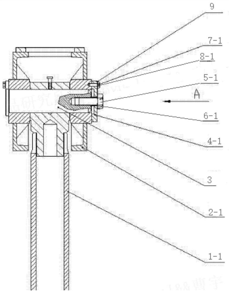
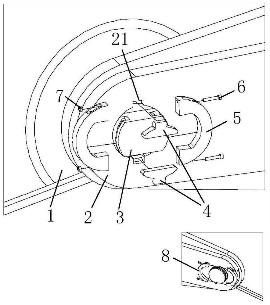
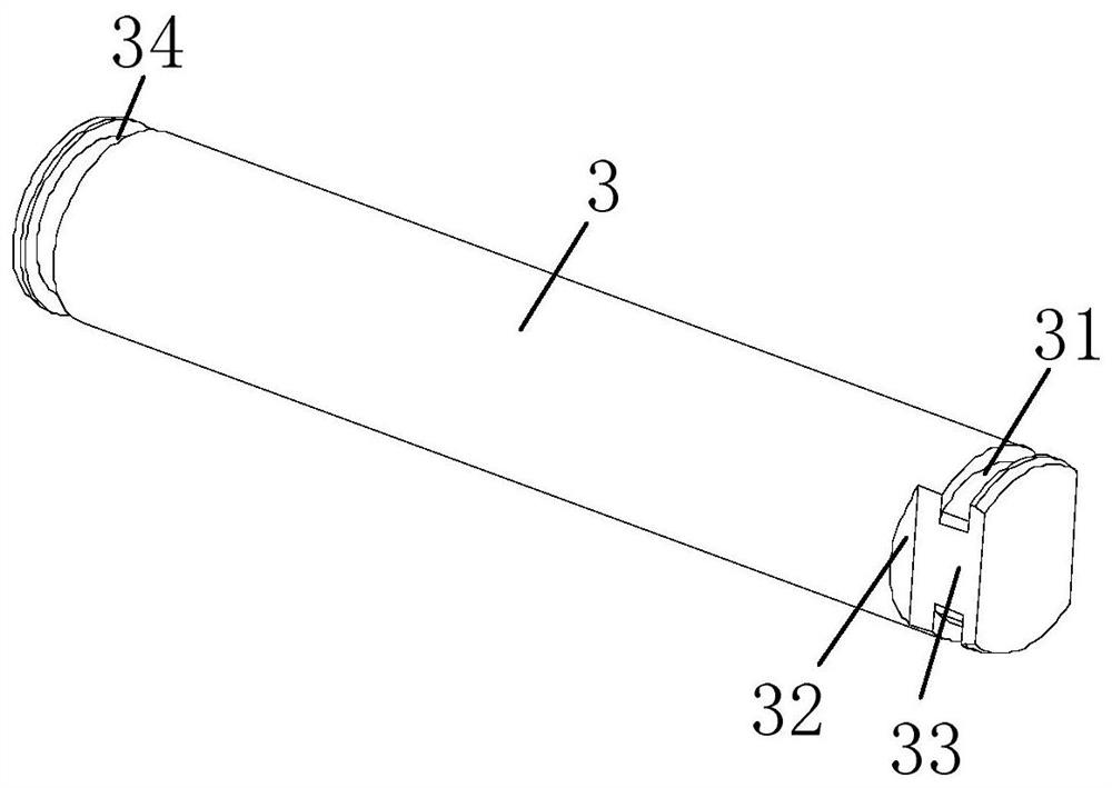
[0052] (1) First pass the pin shaft 3 normally through the rotating part 1 and the base part 2 to realize the hinge connection between the two; (2) Adjust the angle of the pin shaft 3 so that the gap formed by the cutting groove 33 and the stop groove 21 can just fit Put in the stop block 4, and then adjust the extension of the pin shaft 3, so that the stop block 4 can fit the termination surface 32 and not protrude from the surface of the base part 2; (3) buckle the two left stop rings 5 In the first annular groove 31, and each surface can be fit; (4) Use the screw 6 and the nut 7 to fasten the two left stop rings 5 ​​together through the screw groove 53 and the screw through hole 54; (5) On the other side of the pin shaft, the two right stop rings 8 are fastened in the second annular groove 34, and the screws 6 and nuts 7 are also used to fasten the two right stop rings through the screw groove 82 and the screw through hole 83. The rings 8 are fastened together, finalizing t...

Embodiment 2

[0054] A welding-free stop device of the present invention can achieve the stop function described in the present invention by changing the shape of the pin shaft 3, the left stop ring 5, the right stop ring 8 and other components, such as changing the stop block 4 The shape of the ring, the shape of the stop ring, the installation and space arrangement, quantity, position, etc.;

Embodiment 3

[0056] Using a symmetrical structure, the shaft cut-off part can be made into a left-right symmetrical structure, and the same stop block and stop ring are used on both sides;


PUM


Abstract

The invention discloses a welding-free pin shaft and a stop device. The limit of the rotary motion of the pin shaft is realized through the matching of a stop block and the pin shaft, and the effect of limiting the axial movement of the pin shaft is achieved by utilizing the buckling between an annular groove in the pin shaft and left and right stop rings. According to the welding-free pin shaft and the stop device, hole punching in a shaft end surface and a base body part is avoided through assembling, and cracking risks caused by welding are thoroughly avoided; and all components are simple in structure, the overall structure is compact, the occupied space is small, the pin shaft is easy and convenient to disassemble and assemble, and the application range is wide.

Description

technical field [0001] The invention relates to a welding-free pin shaft and a stopper, belonging to the technical field of engineering machinery. Background technique [0002] The relatively rotating parts in construction machinery such as excavators and loaders are generally connected by pin shafts. When the pin shaft is working, it will be subjected to two harmful components of torsional force and channeling force, which will make the pin shaft out of the shaft hole. Playing slips out and causes abnormal wear on the shaft bore surface. Existing pin shafts often use welded baffles on the shaft body and welded stoppers on adjacent parts. Through the cooperative relationship between the baffles and the stoppers, the torsional force and the movement force can be limited, and the pin can be realized. Shaft stop function. [0003] However, in the prior art, the shaft body and the baffle are mainly connected by welding, and the weld will bear the combined force of the above-me...

Claims


Application Information

Patent Timeline
IPC IPC(8): F16B21/10
Inventor 曹宇杨真真王金涛王全永历娜
Owner XCMG EXCAVATOR MACHINERY
Learn More