Waste gas treatment device for industrial boiler

A technology for waste gas treatment devices and industrial boilers, which is applied to the separation of dispersed particles, chemical instruments and methods, and filtration of dispersed particles, which can solve the problems of difficult gas discharge and exhaust gas purification, and achieve the effect of ensuring the quality of purification

Pending Publication Date: 2021-04-20
上饶市江心锅炉有限公司
View PDF7 Cites 4 Cited by
  • Summary
  • Abstract
  • Description
  • Claims
  • Application Information

AI Technical Summary

Problems solved by technology

[0004] In order to overcome the shortcomings of putting a large amount of disinfectant water into the container for collecting waste gas, it is impossible to purify all the waste gas, and the purified gas is not easy to discharge, the technical problem is: to provide a method for rapid adsorption of waste gas, multiple purification and filtration, Naturally discharged industrial boiler waste gas treatment device

Method used


Image

  • Waste gas treatment device for industrial boiler
  • Waste gas treatment device for industrial boiler
  • Waste gas treatment device for industrial boiler

Examples


Embodiment 1

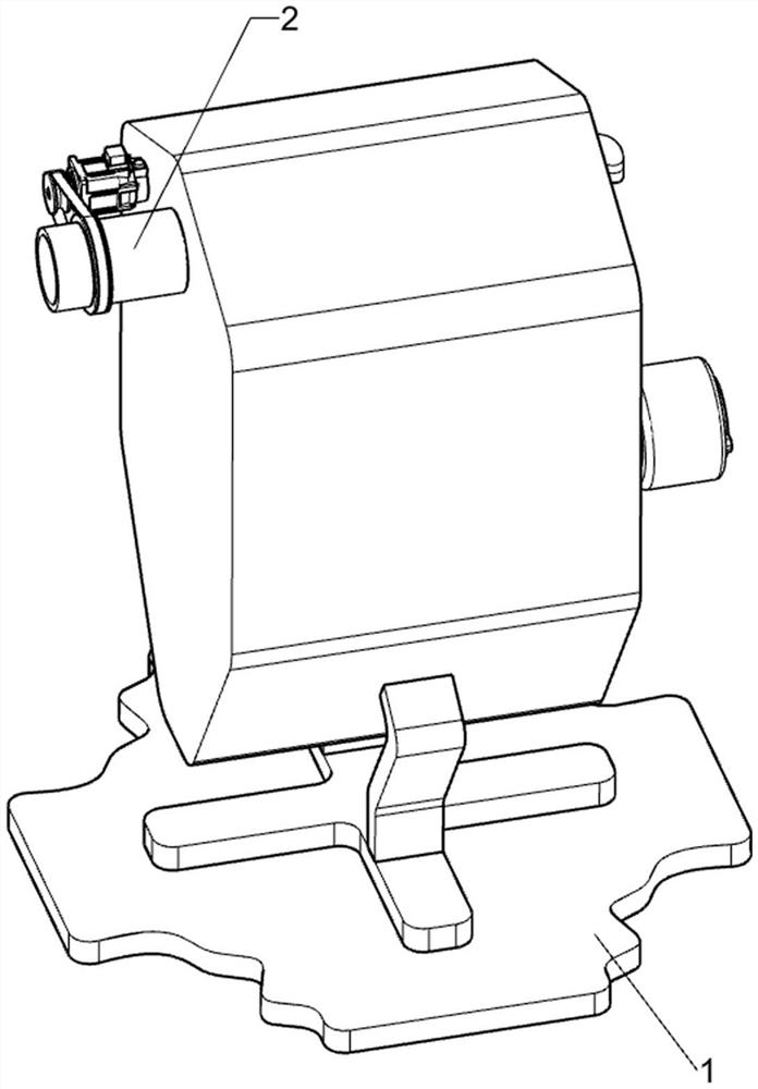
[0056] A waste gas treatment device for industrial boilers, such as Figure 1 to Figure 5 As shown, it includes a base 1 , an exhaust mechanism 2 and a purification mechanism 3 , the top of the base 1 is provided with an exhaust mechanism 2 , and the exhaust mechanism 2 is connected with a purification mechanism 3 .

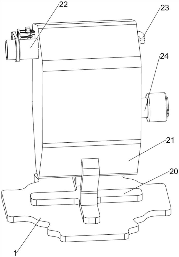
[0057] The exhaust mechanism 2 includes a support 20, a first installation box 21, a first rubber tube 22, a vent pipe 23 and an air outlet pipe 24, the top of the base 1 is provided with a support 20, and the support 20 is provided with a first installation box 21, the first The rear side of the installation box 21 has a working port, the left side of the first installation box 21 is provided with a first rubber tube 22, the right side of the first installation box 21 is provided with a vent pipe 23, and the right side of the first installation box 21 is provided with an outlet. Trachea24.

[0058] The purification mechanism 3 includes a first connection block ...

Embodiment 2

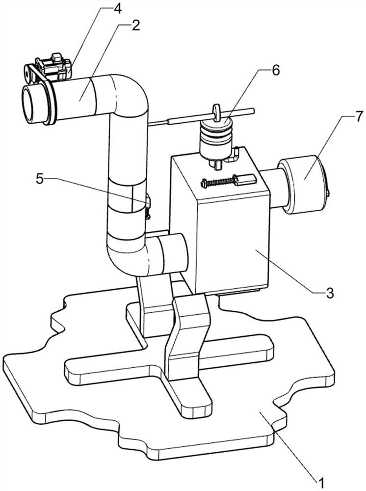
[0061] On the basis of Example 1, such as Figure 6 to Figure 14As shown, a rotating mechanism 4 is also included, and the rotating mechanism 4 includes a servo motor 40, a second rubber tube 41, a belt drive assembly 42, a second connecting block 43 and a first blade 44, and the left side of the first installation box 21 is provided with There is a servo motor 40, a second rubber tube 41 is connected to the left side of the first rubber tube 22, and a second connecting block 43 is rotatably connected to the second rubber tube 41, and a plurality of first blades 44 are arranged in the second connecting block 43 A belt drive assembly 42 is connected between the output shaft of the servo motor 40 and the second connecting block 43 .

[0062] Also include filter mechanism 5, filter mechanism 5 includes filter tube 50, second mounting block 51, second slide block 52 and second spring 53, first rubber tube 22 is slidably provided with filter tube 50, the first rubber tube The tube...


PUM


Abstract

The invention relates to a waste gas treatment device, in particular to a waste gas treatment device for an industrial boiler, and mainly provides a waste gas treatment device for an industrial boiler, wherein the device is used for quickly adsorbing, repeatedly purifying and filtering waste gas and naturally exhausting the waste gas. The waste gas treatment device for the industrial boiler comprises a base, an exhaust mechanism arranged at the top of the base, and a purification mechanism connected to the exhaust mechanism. By arranging the exhaust mechanism and a rotating mechanism, a first blade is driven to rotate to adsorb waste gas, and purification treatment is matched; by arranging the purification mechanism and a filtering mechanism, waste gas is subjected to secondary filtering, and the basic functions of the device are achieved; and by arranging an extrusion mechanism, disinfectant fluid is driven to be sprayed intermittently, and the purification quality is guaranteed.

Description

technical field [0001] The invention relates to a waste gas treatment device, in particular to a waste gas treatment device for industrial boilers. Background technique [0002] Boilers generally use pulverized coal to burn some chemical metal products, and the waste gas discharged from the combustion is directly discharged into the sky through a very high exhaust port, or the waste gas is directly poured with tap water, so that the waste gas enters the water and becomes waste water, because the purification cost is high , Most manufacturers will choose to directly discharge the waste water. This method also pollutes the environment on the basis of wasting raw materials. [0003] In the later stage, a kind of disinfectant water specially designed for purifying waste gas was produced. The staff recycled the waste gas into a large container, and then put the disinfectant water into the container. This method cannot purify all the waste gas, and the purified gas is not easy to ...

Claims


Application Information

Patent Timeline
IPC IPC(8): B01D53/06B01D46/24B01D46/10B01D53/79
Inventor 黄正涛
Owner 上饶市江心锅炉有限公司
Why Eureka
Try Eureka